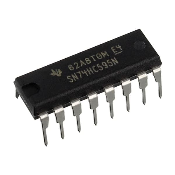
74HC595 8-Bit Shift Register (DIP-16)
Estimated delivery
Sat, 1 Aug
Shipping benefit
Free shipping ₹1,499+*
*Standard delivery; eligible order value applies.
The 74HC595 is an essential 8-bit shift register that solves one of the most common problems in hardware design: running out of microcontroller pins. By using just three digital pins (Data, Clock, and Latch) from your development board, this IC gives you eight completely independent digital output pins. Need even more? You can daisy-chain multiple 74HC595 chips together to control 16, 24, or even 64 outputs—like massive LED arrays or multiple relays—without using any extra pins on your main microcontroller. Packaged in a breadboard-friendly DIP-16 format, it is a must-have for expanding your digital I/O.
Secure payments
Expert support
Easy replacements
Everything you need to know
Product details
No matter how powerful your microcontroller is, you will eventually run out of GPIO pins. If you are building an intricate custom buffer board, a complex PICO IOT setup, or just trying to wire up a massive array of LEDs, connecting each component directly to your main board quickly becomes impossible.
The 74HC595 8-Bit Shift Register is the standard, elegant solution to this problem. It operates on a "Serial-In, Parallel-Out" (SIPO) protocol. Instead of toggling eight separate pins on your microcontroller, you send a single string of data (1s and 0s) through just one data pin. The 74HC595 catches this string in its internal memory, and when you trigger the "Latch" pin, it instantly outputs that data across its eight physical pins (Q0 to Q7).
What makes this IC truly powerful is its cascading ability. It features a dedicated "Serial Out" pin. If you connect this to the "Data In" of a second 74HC595, the data literally "shifts" from one chip to the next. You can daisy-chain dozens of these chips together to control hundreds of outputs, all while still only using three pins on your main microcontroller.
Whether you are controlling a bank of relays for an industrial dashboard or multiplexing a 7-segment display, this tiny IC keeps your wiring clean and your code efficient.
Developer Note: The 74HC595 is highly versatile and works perfectly across a wide voltage range (2.0V to 6.0V). This means you can safely use it with standard 5V logic (like an Arduino Uno) or directly interface it with modern 3.3V logic boards (like an ESP32 or ESP8266) without needing a logic level converter.
Key Features
- Pin Expansion: Converts 3 serial inputs (Data, Clock, Latch) into 8 parallel outputs.
- Cascadable: Daisy-chain multiple ICs together for unlimited output expansion.
- Wide Operating Voltage: 2.0V to 6.0V DC (Fully compatible with 5V Arduino and 3.3V ESP32/ARM boards).
- High Output Drive: Each output pin can source or sink up to 35mA, easily enough to drive standard LEDs directly.
- Low Power Consumption: Uses only 80µA of quiescent current, making it great for battery-powered or remote projects.
- Package: Standard 16-pin DIP (Dual In-line Package), perfect for solderless breadboards or custom PCBs.
Pinout Guide
- Q1 to Q7 (Pins 1-7): Parallel Data Outputs 1 through 7.
- GND (Pin 8): Common Ground.
- Q7' (Pin 9): Serial Data Output (Connect this to the Data Input of the next 74HC595 if daisy-chaining).
- SRCLR (Pin 10): Master Reset. Pull LOW to clear the shift register. (Usually tied directly to VCC if unused).
- SRCLK (Pin 11): Shift Register Clock. Each time this pin goes HIGH, data is shifted one step.
- RCLK (Pin 12): Storage Register Clock (Latch). When this goes HIGH, the internal data is pushed to the physical output pins.
- OE (Pin 13): Output Enable. Active LOW. (Tie to Ground to enable the outputs. Pull HIGH to disable outputs).
- SER (Pin 14): Serial Data Input. This is where your microcontroller sends the 1s and 0s.
- Q0 (Pin 15): Parallel Data Output 0.
- VCC (Pin 16): Positive Power Supply (2.0V to 6.0V).
Built by the community
Customer reviews
Real builds, honest feedback, and photos from people using 74HC595 8-Bit Shift Register (DIP-16).
Picked for this product
You might also like
 Sale 46%
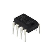
LM386 Low Voltage Audio Power Amplifier IC (DIP-8)
Rs 35
Rs 65
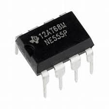
NE555 Precision Timer IC
Rs 20
 Sale 34%
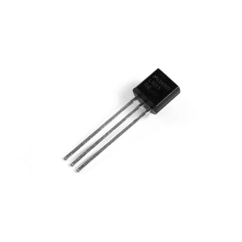
LM35DZ Precision Analog Temperature Sensor IC (TO-92)
Rs 65
Rs 99
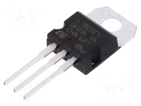 Sale 25%
L7805CV 5V Positive Linear Voltage Regulator IC (TO-220)
Rs 45
Rs 60
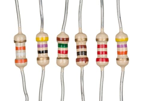 Sale 50%
470 Ohm Resistor | 470Ω Through-Hole Resistor for Electronics Projects
Rs 2
Rs 4
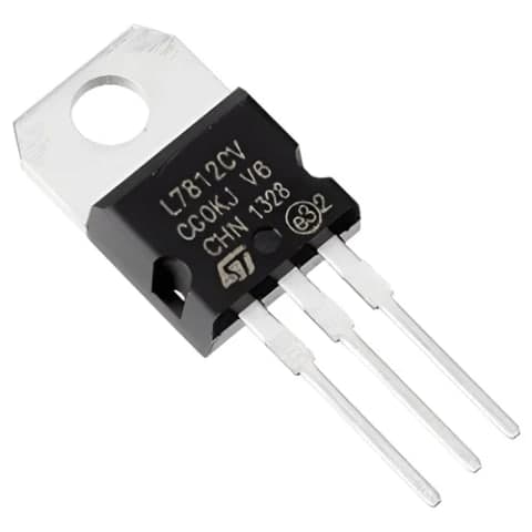 Sale 25%
L7812CV 12V Positive Linear Voltage Regulator IC (TO-220)
Rs 45
Rs 60
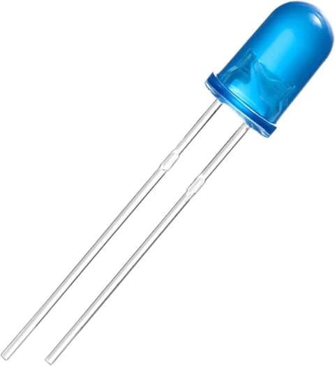 Sale 25%
5mm Blue LED | Round Indicator LED for Electronics Projects
Rs 2.64
Rs 3.5
Sale 50%1K Ohm Resistor | 1kΩ Through-Hole Resistor for Electronics Projects
Rs 2
Rs 4
 Sale 13%
L293D Dual H-Bridge Motor Driver IC (DIP-16)
Rs 13
Rs 15
LM317T Adjustable Positive Linear Voltage Regulator IC (TO-220)
Rs 45