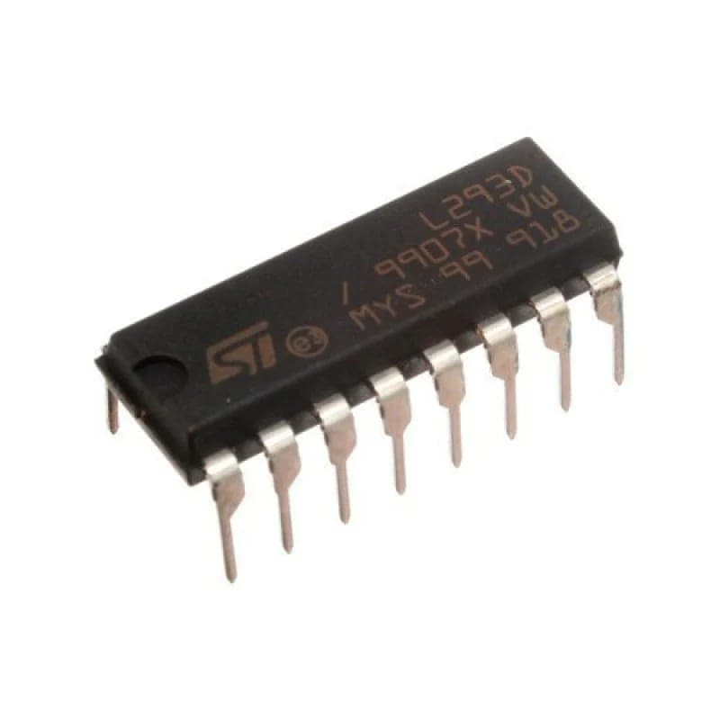
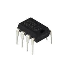
L293D Dual H-Bridge Motor Driver IC (DIP-16)
Estimated delivery
Sat, 1 Aug
Shipping benefit
Free shipping ₹1,499+*
*Standard delivery; eligible order value applies.
The L293D is the most popular motor driver IC for beginners and hobbyists. Packaged in a breadboard-friendly 16-pin DIP format, it acts as a crucial bridge between your microcontroller's low-power logic signals and the high-power demands of DC motors. It contains two built-in H-bridges, allowing you to simultaneously control the speed and direction of two DC motors, or precisely drive one bipolar stepper motor. With internal flyback diodes to protect your expensive development boards from voltage spikes, it is the safest and easiest way to give your Arduino or ESP32 projects physical motion.
Secure payments
Expert support
Easy replacements
Everything you need to know
Product details
Microcontrollers like the Arduino Uno or ESP32 are brains, not muscle. They can only output a tiny amount of current (usually around 20-40mA)—barely enough to light up an LED. If you connect a standard DC motor directly to a microcontroller pin, the motor will instantly draw too much current and permanently fry your board.
That is exactly why you need the L293D Motor Driver IC.
This chip acts as an amplifier and a switch. You provide the motor's heavy power supply (up to 36V) directly to the IC, and then use the low-power 5V or 3.3V digital pins from your microcontroller to tell the chip when to send that heavy power to the motors.
Because it features a Dual H-Bridge design, it doesn't just turn motors on and off; it can reverse their polarity. This means you can drive two DC motors forward, backward, or stop them completely independent of each other. It is the absolute foundation for building 2-wheel drive rovers, robotic arms, and automated blinds.
Important Safety Feature: The "D" in L293D stands for "Diodes." Unlike the older L293 or L298 ICs, this specific chip has built-in clamping diodes. When a motor stops spinning, it generates a nasty reverse voltage spike (Back EMF). The L293D safely absorbs this spike, preventing it from travelling back into your microcontroller and destroying it.
Key Features
- Motor Control: Can independently drive two DC motors or one bipolar Stepper motor.
- Operating Voltage (Motors): Accepts a wide motor power supply from 4.5V up to 36V DC.
- Logic Voltage: Compatible with standard 5V logic (Arduino) and safely triggers from 3.3V logic (ESP32/Raspberry Pi).
- Output Current: Delivers 600mA of continuous current per channel, with peak spikes up to 1.2A.
- Package: Standard 16-pin DIP (Dual In-line Package) - Snaps perfectly into standard breadboards and zero-PCBs.
- Protection: Features internal thermal shutdown (it turns off if it gets too hot) and internal ESD protection.
Pinout Guide
- Enable 1,2: Turns on the left side of the chip (Motors 1). Connect to a PWM pin for speed control!
- Input 1: Logic from microcontroller (Controls Motor 1 direction).
- Output 1: Connect to Motor 1 (+) terminal.
- GND: Connect to common ground (Also acts as a heat sink).
- GND: Connect to common ground.
- Output 2: Connect to Motor 1 (-) terminal.
- Input 2: Logic from microcontroller (Controls Motor 1 direction).
- VCC2 (Vs): Motor Power Supply (e.g., your 9V or 12V battery).
- Enable 3,4: Turns on the right side of the chip (Motor 2).
- Input 3: Logic from microcontroller (Controls Motor 2 direction).
- Output 3: Connect to Motor 2 (+) terminal.
- GND: Connect to common ground.
- GND: Connect to common ground.
- Output 4: Connect to Motor 2 (-) terminal.
- Input 4: Logic from microcontroller (Controls Motor 2 direction).
- VCC1 (Vss): Logic Power Supply (Connect to the 5V pin on your microcontroller).
Built by the community
Customer reviews
Real builds, honest feedback, and photos from people using L293D Dual H-Bridge Motor Driver IC (DIP-16).
Picked for this product
You might also like
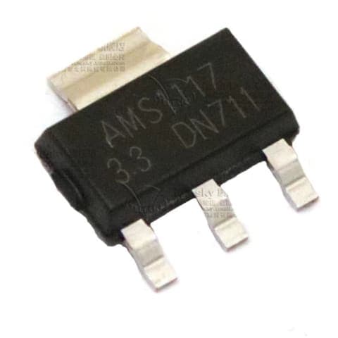
AMS1117 3.3V 1A Low Dropout (LDO) Voltage Regulator (SOT-223)
Rs 12
 Sale 50%
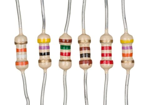
470 Ohm Resistor | 470Ω Through-Hole Resistor for Electronics Projects
Rs 2
Rs 4
 Sale 25%
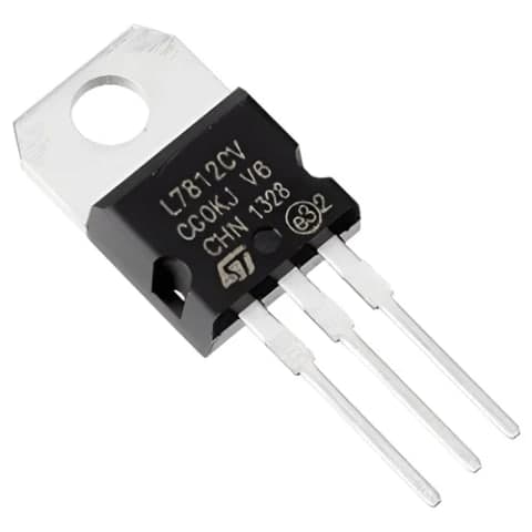
L7812CV 12V Positive Linear Voltage Regulator IC (TO-220)
Rs 45
Rs 60
 Sale 25%
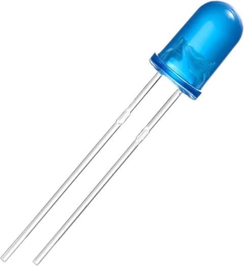
5mm Blue LED | Round Indicator LED for Electronics Projects
Rs 2.64
Rs 3.5
Sale 50%1K Ohm Resistor | 1kΩ Through-Hole Resistor for Electronics Projects
Rs 2
Rs 4
 Sale 7%
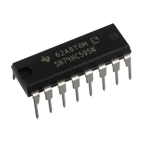
74HC595 8-Bit Shift Register (DIP-16)
Rs 28
Rs 30
 Sale 34%
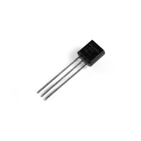
LM35DZ Precision Analog Temperature Sensor IC (TO-92)
Rs 65
Rs 99
 Sale 25%
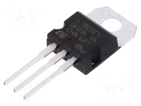
L7805CV 5V Positive Linear Voltage Regulator IC (TO-220)
Rs 45
Rs 60
 Sale 46%
LM386 Low Voltage Audio Power Amplifier IC (DIP-8)
Rs 35
Rs 65
NE555 Precision Timer IC
Rs 20