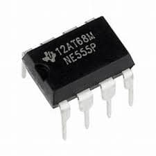
NE555 Precision Timer IC
Estimated delivery
Sat, 1 Aug
Shipping benefit
Free shipping ₹1,499+*
*Standard delivery; eligible order value applies.
The NE555 is arguably the most famous and widely used integrated circuit in the history of electronics. Packaged in a standard breadboard-friendly DIP-8 format, it is a precision timing device capable of producing accurate time delays, pulses, and oscillations without writing a single line of code. Whether you need to debounce a physical switch, build a custom PWM motor controller, or create an LED flasher, the 555 timer handles it all natively in hardware. Capable of sourcing or sinking up to 200mA, it can directly drive small relays, buzzers, and LEDs, making it a mandatory component in any hardware developer's toolkit.
Secure payments
Expert support
Easy replacements
Everything you need to know
Product details
Before the era of microcontrollers and writing software to blink an LED, there was the NE555 Timer IC. It remains a foundational building block of analog and digital electronics, allowing you to generate precise timing events, delays, and continuous square waves purely through hardware.
The beauty of the 555 timer lies in its simplicity and versatility. By connecting different combinations of resistors and capacitors to its pins, you can dictate exactly how the chip behaves. It gets its name from the three internal 5kΩ resistors used to create a voltage divider, giving it highly stable and predictable threshold levels.
It operates in three primary modes:
- Astable Mode (Oscillator): The IC runs in a continuous loop, generating a steady square wave. Perfect for creating warning sirens, LED strobes, or custom clock pulses for digital logic circuits.
- Monostable Mode (One-Shot): The IC outputs a single, precisely timed high pulse when triggered. This is the ultimate solution for "switch debouncing" (cleaning up the noisy signal from a mechanical button before it reaches your ESP32) or creating a system that stays on for exactly 10 seconds after a button press.
- Bistable Mode (Flip-Flop): The IC acts as a simple memory state, staying HIGH or LOW until an external signal tells it to switch.
Unlike standard logic chips that can only handle tiny amounts of current, the NE555 is a workhorse. Its output pin can source or sink up to 200mA, meaning you don't even need an external transistor to drive standard LEDs, small DC motors, or 5V relays.
Key Features
- Operating Voltage: 4.5V to 15V DC (Highly versatile, works natively with standard 5V logic and 12V automotive setups).
- High Output Drive: Capable of sourcing or sinking up to 200mA directly from the Output pin.
- Timing Range: Extremely wide timing capabilities, from sharp microsecond pulses up to hour-long delays.
- Temperature Stability: Excellent stability of 0.005% per °C change, meaning your timing won't drift significantly if the board gets warm.
- Adjustable Duty Cycle: Fine-tune the exact ON and OFF times of your oscillations.
- Package: Standard DIP-8 (Dual In-line Package), perfectly pitched for solderless breadboards and standard zero-PCBs.
Pinout Guide
- GND (Ground): Connect to the common ground of your circuit (0V).
- TRIG (Trigger): A momentary drop below 1/3 of the supply voltage here starts the timing cycle.
- OUT (Output): Delivers the timed pulse or oscillation. (HIGH = near VCC, LOW = near 0V).
- RESET: Pull this pin LOW (to Ground) to instantly interrupt the timing cycle and force the output LOW. Keep tied to VCC if unused.
- CONT (Control Voltage): Provides access to the internal voltage divider. Usually bypassed to ground with a 10nF (0.01µF) capacitor to prevent electrical noise from messing up your timing.
- THRES (Threshold): Detects when the voltage on your external timing capacitor reaches 2/3 of VCC, ending the timing cycle.
- DISCH (Discharge): Connected to an internal transistor that discharges your external timing capacitor to ground to restart the cycle.
- VCC (Power): Positive supply voltage input (4.5V to 15V).
Built by the community
Customer reviews
Real builds, honest feedback, and photos from people using NE555 Precision Timer IC.
Picked for this product
You might also like
 Sale 13%
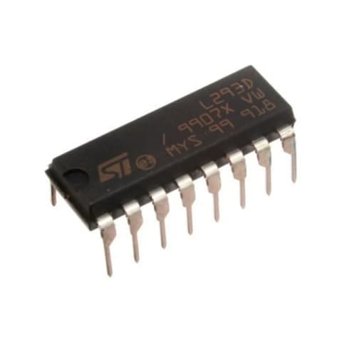
L293D Dual H-Bridge Motor Driver IC (DIP-16)
Rs 13
Rs 15
 Sale 25%
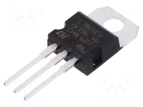
L7805CV 5V Positive Linear Voltage Regulator IC (TO-220)
Rs 45
Rs 60
 Sale 46%
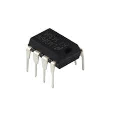
LM386 Low Voltage Audio Power Amplifier IC (DIP-8)
Rs 35
Rs 65
 Sale 50%
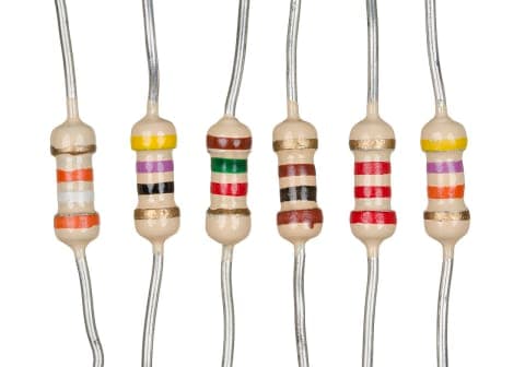
470 Ohm Resistor | 470Ω Through-Hole Resistor for Electronics Projects
Rs 2
Rs 4
 Sale 25%
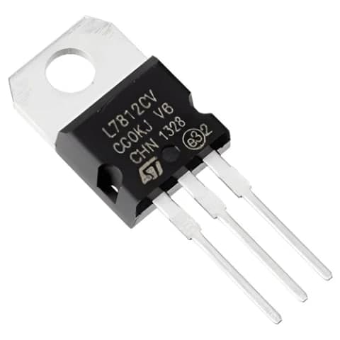
L7812CV 12V Positive Linear Voltage Regulator IC (TO-220)
Rs 45
Rs 60
 Sale 25%
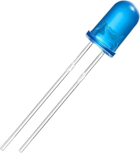
5mm Blue LED | Round Indicator LED for Electronics Projects
Rs 2.64
Rs 3.5
Sale 50%1K Ohm Resistor | 1kΩ Through-Hole Resistor for Electronics Projects
Rs 2
Rs 4
 Sale 7%
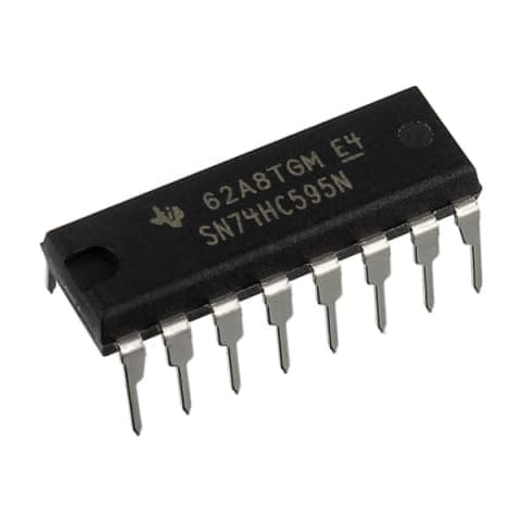
74HC595 8-Bit Shift Register (DIP-16)
Rs 28
Rs 30
 Sale 34%
LM35DZ Precision Analog Temperature Sensor IC (TO-92)
Rs 65
Rs 99
AMS1117 3.3V 1A Low Dropout (LDO) Voltage Regulator (SOT-223)
Rs 12