📝Title: Arduino Basics: Your First LED Blink (Step‑by‑Step for Absolute Beginners)
So you’ve unboxed your Arduino, plugged it in once or twice, and now it’s staring back at you like, “Okay, what next?” In this beginner-friendly tutorial, you’ll build the classic **LED blink** project – the “Hello, World” of electronics – and understand every step along the way.
Arduino Basics: Your First LED Blink (Step-by-Step for Absolute Beginners)
So you've unboxed your Arduino, plugged it in once or twice, and now it's staring back at you like, "Okay, what next?"
In this beginner-friendly tutorial, you'll build the classic LED blink project – the "Hello, World" of electronics – and understand every step along the way.
🧩 What You'll Need

To follow this tutorial, gather these basic components:
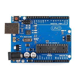
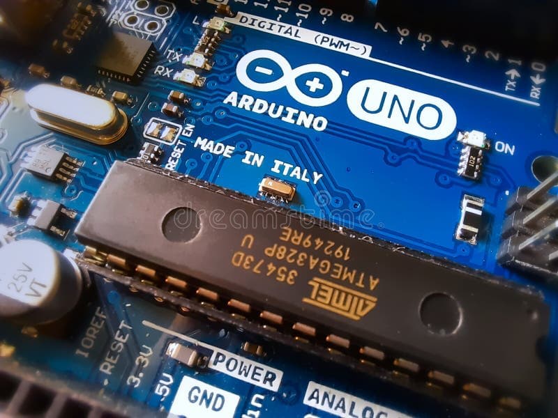
- 1× Arduino Uno (or compatible board)
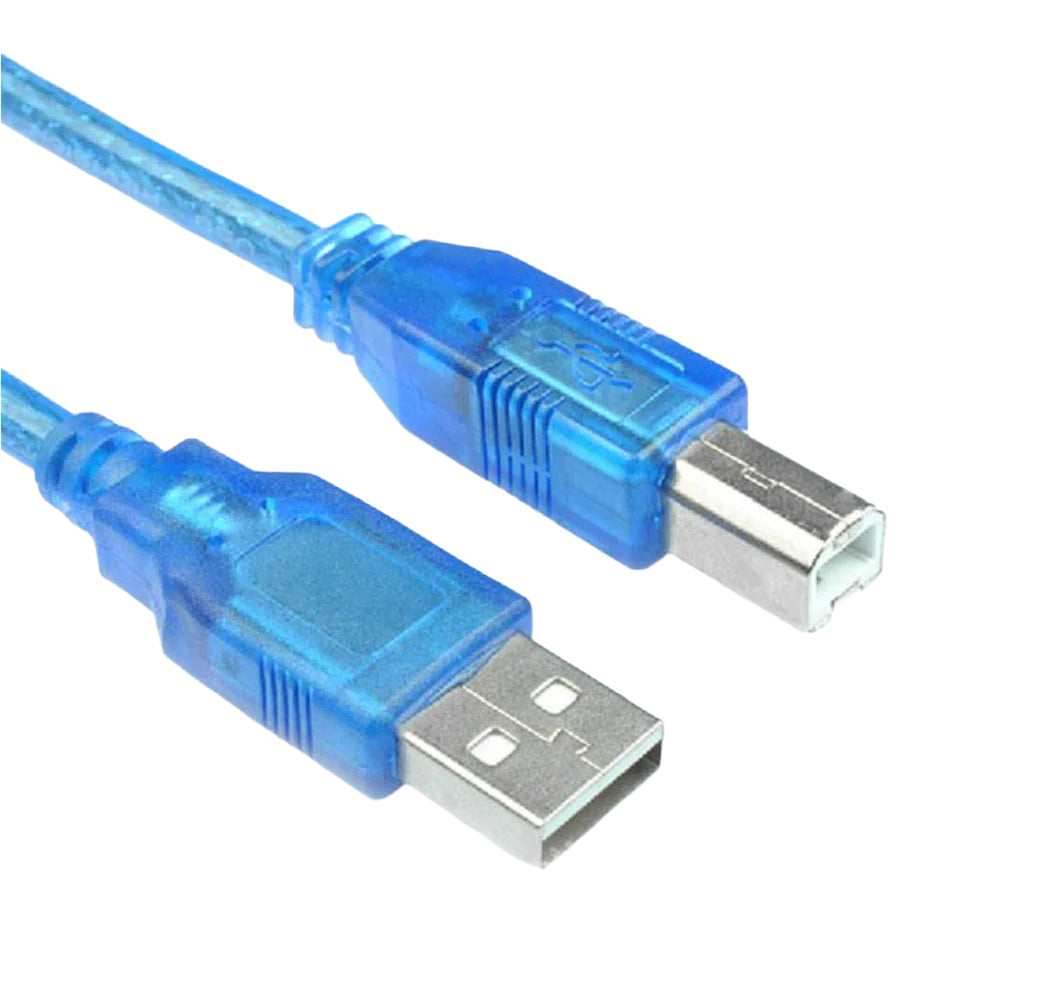
- 1× USB cable (Type A to Type B, the classic printer-style cable)
- 1× Breadboard
- 1× LED (any color)
- 1× 220 Ω resistor (or 330 Ω – anything in that range is fine)
- 2–3× Male-to-male jumper wires
🔌 Step 1: Connect Your Arduino to Your PC
Before we wire anything, let's make sure your Arduino can talk to your computer.
- Plug the USB cable into your Arduino.
- Connect the other end to your laptop/PC.
- The power LED on the Arduino should turn on, and you may see the built-in LED near pin 13 blinking.
Next, install the Arduino IDE (if you haven't already):
- Go to the official Arduino website.
- Download the IDE for your OS (Windows, macOS, or Linux).
- Install and open it, then select:
Tools→Board→Arduino UnoTools→Port→ Select the COM/serial port that shows your Arduino
🧱 Step 2: Understand the Circuit You're Building
You're going to connect an external LED to one of the Arduino's digital pins, then toggle that pin HIGH/LOW in code to turn the LED on and off.
Key ideas:
- The digital pin (we'll use pin 8) will provide 5 V when HIGH and 0 V when LOW.
- The resistor protects the LED from drawing too much current.
- Current will flow:
Pin 8 → Resistor → LED → GND.
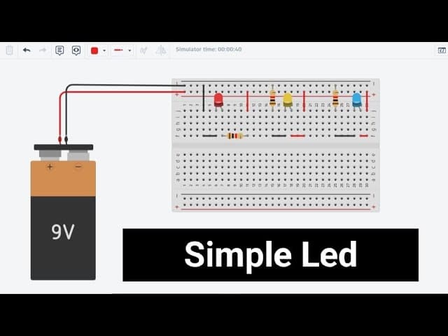
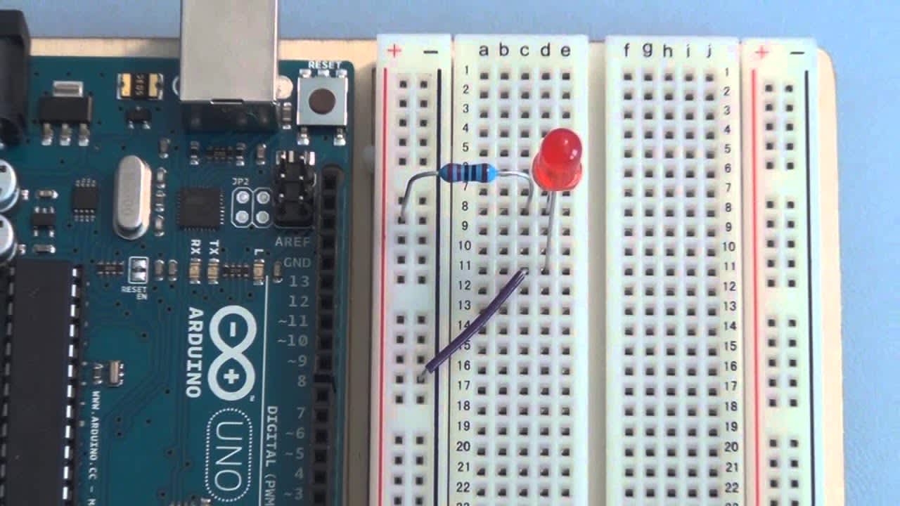
🪛 Step 3: Wire the LED on the Breadboard
Now let's build the physical circuit.
Follow these steps:
- Place the LED on the breadboard so its two legs are in different rows.
- The longer leg (anode) is the positive side (goes to the Arduino pin via resistor).
- The shorter leg (cathode) is the negative side (goes to GND).
- Connect one end of the 220 Ω resistor to the same row as the anode (longer leg) of the LED.
- Connect the other end of the resistor to digital pin 8 on the Arduino using a jumper wire.
- Connect the cathode (shorter leg) of the LED to GND on the Arduino using another jumper wire.
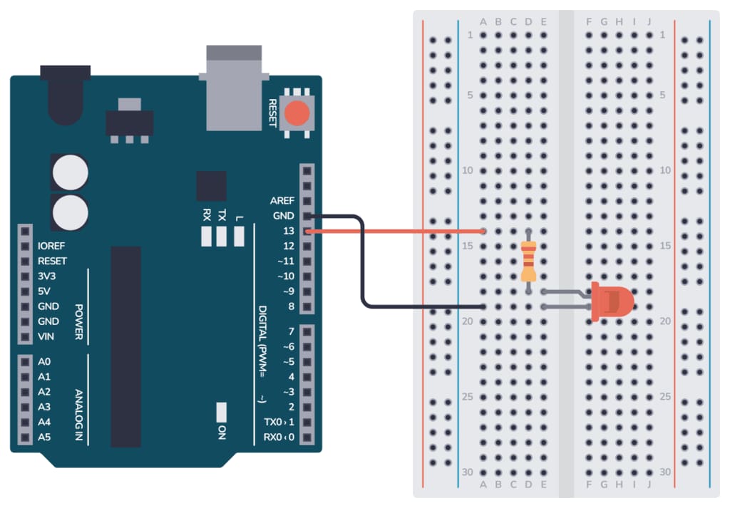
At this point, your Arduino, breadboard, LED, resistor, and wires should resemble a simple T-shaped connection: Pin 8 → Resistor → LED → GND.
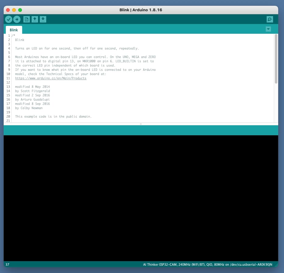
💻 Step 4: Write the Blink Code
Open the Arduino IDE and type (or paste) this simple sketch:
// Simple LED Blink on pin 8

const int LED_PIN = 8;

void setup() {
  pinMode(LED_PIN, OUTPUT);  // Set pin 8 as an output
}

void loop() {
  digitalWrite(LED_PIN, HIGH);  // Turn LED ON
  delay(500);                   // Wait 500 ms
  digitalWrite(LED_PIN, LOW);   // Turn LED OFF
  delay(500);                   // Wait 500 ms
}
What this code does:
setup()runs once and tells the Arduino that pin 8 will be used as an output.loop()runs forever:- Turns the LED on.
- Waits 500 ms (half a second).
- Turns the LED off.
- Waits another 500 ms.
- Repeats forever.
🚀 Step 5: Upload and Test
- In the Arduino IDE, click the ✔ (Verify) button to compile your code.
- If there are no errors, click the ➡ (Upload) button.
- Look at your breadboard: the LED should now blink on and off every half second.
If it doesn't blink:
- Double-check that the long leg of the LED goes toward the resistor/pin 8.
- Confirm that the short leg goes to GND.
- Make sure the correct board and port are selected under
Tools.
🔍 Step 6: Experiment with Timing and Pins
Once it's working, start experimenting:
- Change
delay(500);todelay(100);to make it blink faster. - Try
delay(1000);for a slower, 1-second blink. - Move the wire from pin 8 to pin 7, update
LED_PINaccordingly, and upload again.
This simple exploration teaches you:
- How digital pins behave.
- How code and hardware interact in real time.
- How small changes in code affect physical behavior.
🎓 Where to Go Next
Now that you've mastered the LED blink, you're ready for:
- Multiple LEDs with different blink patterns.
- Buttons to control the LED.
- Using PWM pins to fade the LED in and out.
- Driving buzzers, relays, or sensors using the same digital output logic.
Each of these projects builds on the exact concepts you just used: digital outputs, basic wiring, and simple timing.