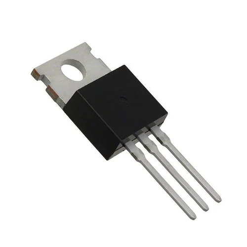
LM317T Adjustable Positive Linear Voltage Regulator IC (TO-220)
Estimated delivery
Fri, 31 Jul
Shipping benefit
Free shipping ₹1,499+*
*Standard delivery; eligible order value applies.
The LM317T is an incredibly versatile, adjustable 3-terminal positive voltage regulator. Unlike fixed regulators, it allows you to dial in the exact voltage your project needs, anywhere from 1.25V up to 37V, using just two external resistors. It is a must-have component for building custom power supplies or variable benchtop power modules. Key Features: Fully Adjustable: Output voltage can be set anywhere from 1.25V to 37V DC. High Current Output: Capable of supplying in excess of 1.5A (with proper heatsinking). Robust Protection: Features internal short-circuit current limiting and thermal overload protection. Versatile Use Cases: Perfect for custom voltage rails, LED drivers, or custom battery charging circuits.
Secure payments
Expert support
Easy replacements
Everything you need to know
Product details
Overview
The LM317T is the gold standard for adjustable linear regulation. Whether you need a specific 3.3V for a microcontroller, 9V for a guitar pedal, or 4.2V for a charging circuit, this IC allows you to tune the output with precision.
Housed in a TO-220 package, it can be easily mounted to a heatsink for high-power applications. It is significantly more flexible than fixed-voltage regulators (like the 7805), allowing your power supply to grow and adapt to your project's specific needs.
Technical Specifications
| Feature | Specification |
|---|---|
| Output Voltage Range | 1.25V to 37V DC |
| Output Current | 1.5A (Typical) |
| Input-Output Differential | 3V to 40V |
| Line Regulation | 0.01% / V |
| Load Regulation | 0.1% |
| Package Type | TO-220 (Through-hole) |
Basic Application Circuit
To get the LM317T running, you only need a few external components. The following diagram shows the standard configuration for a variable power supply:

Component Selection
- C1 (Input Capacitor): 0.1μF ceramic capacitor to filter input noise.
- C2 (Output Capacitor): 1μF tantalum or 10μF electrolytic for improved transient response.
- R1: Typically a fixed 240Ω or 330Ω resistor.
- R2: A potentiometer (often 5kΩ or 10kΩ) to adjust the output voltage.
Pinout Configuration
Holding the flat side with text facing you:
- ADJ (Adjust): Connects to the junction of R1 and R2.
- VOUT (Output): The regulated output voltage.
- VIN (Input): The unregulated input supply.
⚠️ Warning: The pinout is NOT the same as a 7805 regulator. Pin 1 is Adjust, not Input. Always double-check your connections before powering up.
Calculating Output Voltage
The output voltage is determined by the ratio of the two resistors ($R_1$ and $R_2$). Use the following formula to calculate your target:
$V_{OUT} = 1.25V \times (1 + \frac{R_2}{R_1})$
Common Setups:
- For 3.3V Output: Use $R_1 = 240Ω$ and $R_2 = 390Ω$
- For 5V Output: Use $R_1 = 240Ω$ and $R_2 = 720Ω$
- For 12V Output: Use $R_1 = 240Ω$ and $R_2 = 2.06kΩ$
💡 Design Tip: Linear regulators generate heat based on the voltage drop ($V_{IN} - V_{OUT}$) multiplied by the current. If you are dropping 12V to 3.3V at high current, a TO-220 Heatsink is mandatory.
Built by the community
Customer reviews
Real builds, honest feedback, and photos from people using LM317T Adjustable Positive Linear Voltage Regulator IC (TO-220).
Picked for this product
You might also like
 Sale 25%
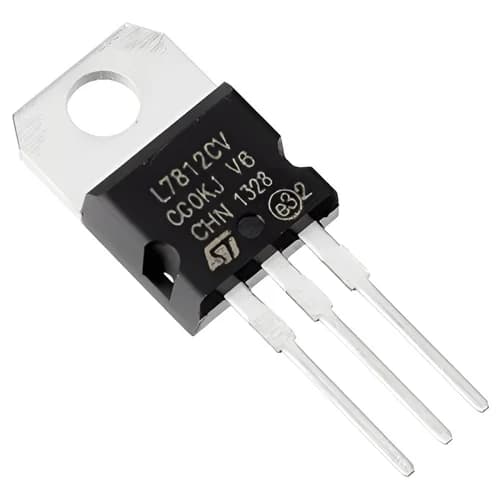
L7812CV 12V Positive Linear Voltage Regulator IC (TO-220)
Rs 45
Rs 60
 Sale 25%
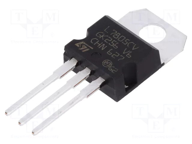
L7805CV 5V Positive Linear Voltage Regulator IC (TO-220)
Rs 45
Rs 60
 Sale 46%
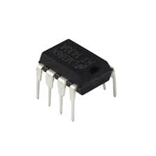
LM386 Low Voltage Audio Power Amplifier IC (DIP-8)
Rs 35
Rs 65
 Sale 50%
470 Ohm Resistor | 470Ω Through-Hole Resistor for Electronics Projects
Rs 2
Rs 4
 Sale 25%
5mm Blue LED | Round Indicator LED for Electronics Projects
Rs 2.64
Rs 3.5
Sale 50%1K Ohm Resistor | 1kΩ Through-Hole Resistor for Electronics Projects
Rs 2
Rs 4
 Sale 7%
74HC595 8-Bit Shift Register (DIP-16)
Rs 28
Rs 30
 Sale 13%
L293D Dual H-Bridge Motor Driver IC (DIP-16)
Rs 13
Rs 15
 Sale 34%
LM35DZ Precision Analog Temperature Sensor IC (TO-92)
Rs 65
Rs 99
AMS1117 3.3V 1A Low Dropout (LDO) Voltage Regulator (SOT-223)
Rs 12