1 / 2
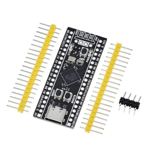
1 / 2STM32F103C8T6 "Blue Pill" ARM Cortex-M3 Development Board (Seperate Headers)
Estimated delivery
Sat, 1 Aug
Shipping benefit
Free shipping ₹1,499+*
*Standard delivery; eligible order value applies.
Step up from 8-bit microcontrollers to the incredible speed and power of the 32-bit ARM Cortex-M3 architecture. The STM32 "Blue Pill" runs at a blazing 72MHz, offering vastly superior processing power, memory, and peripheral support compared to standard Arduino boards. Featuring built-in hardware for CAN bus, multiple UARTs, and advanced timers, it is the ultimate low-cost embedded computing solution. Whether you are designing industrial motor controllers, automotive diagnostics (VHMS), or high-speed drone flight controllers, this board delivers professional-grade performance in a tiny, breadboard-friendly package.
Secure payments
Expert support
Easy replacements
Everything you need to know
Product details
When your robotics, IoT, or industrial project outgrows the speed and memory limits of an Arduino Uno or Nano, it is time to upgrade to ARM architecture. The STM32F103C8T6, universally known as the "Blue Pill," is the bridge between hobbyist electronics and professional embedded systems engineering.
Running at a lightning-fast 72MHz, this board handles complex floating-point math, high-speed sensor fusion, and Real-Time Operating Systems (RTOS) without breaking a sweat. What truly sets the Blue Pill apart is its industrial-grade peripheral support. Unlike basic microcontrollers, it features dedicated hardware for CAN 2.0B (Controller Area Network)—making it an absolute necessity for automotive applications, vehicle health monitoring, and robust industrial automation.
It also boasts three hardware UARTs, two I2C buses, and two SPI buses, ensuring you will never run out of communication channels when connecting multiple sensors, GPS modules, or wireless transceivers.
Programming Note: While this board can be programmed using the Arduino IDE via a USB-to-TTL adapter, we highly recommend purchasing an ST-Link V2 Programmer (sold separately). The ST-Link allows for true hardware debugging, letting you step through your code line-by-line to find complex errors.
Key Features
- Microcontroller Core: 32-bit ARM Cortex-M3 CPU.
- Clock Speed: 72 MHz (Massively outperforming 16MHz 8-bit boards).
- Memory: 64 KB Flash memory and 20 KB SRAM.
- Operating Voltage: 3.3V Logic (Note: Many I/O pins are 5V tolerant, making it easy to interface with older 5V sensors).
- Communication Interfaces: 3x USART, 2x I2C, 2x SPI, 1x CAN 2.0B, 1x USB 2.0 Full Speed.
- Timers: Three 16-bit general-purpose timers and one advanced-control timer (perfect for precise motor PWM generation).
- ADC: Two fast 12-bit Analog-to-Digital Converters (0-3.6V range) with up to 10 channels.
- RTC: Integrated Real-Time Clock with dedicated 32.768 kHz oscillator support.
Pinout Highlights
- 3.3V / GND: Power and Ground.
- 5V / VIN: External Power Input.
- PA9 (TX) / PA10 (RX): USART1 (Default pins for serial bootloader programming).
- PA11 / PA12: USB D- and USB D+ (or CAN RX / CAN TX).
- PB6 (SCL) / PB7 (SDA): I2C1 Communication.
- SWDIO / SWCLK: Serial Wire Debug pins (Connect directly to ST-Link V2 for programming and debugging).
- PC13: Connected to the onboard green user LED.
- BOOT0 / BOOT1 Jumpers: Used to select the boot mode (Flash Memory, System Memory, or SRAM).
Built by the community
Customer reviews
Real builds, honest feedback, and photos from people using STM32F103C8T6 "Blue Pill" ARM Cortex-M3 Development Board (Seperate Headers).
Picked for this product
You might also like
 Sale 7%
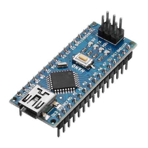
Arduino Nano V3.0 CH340 Development Board (Upgraded Type-C)
Rs 399
Rs 429
 Sale 9%
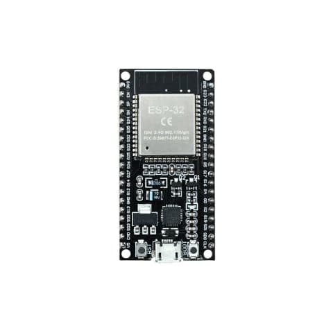
ESP32-WROOM-32 DevKit V1 (Wi-Fi + Bluetooth IoT Board)
Rs 499
Rs 549
 Sale 7%
STM32F401CCU6 Black Pill Development Board - High-Performance ARM Cortex-M4
Rs 500
Rs 540
 Sale 36%
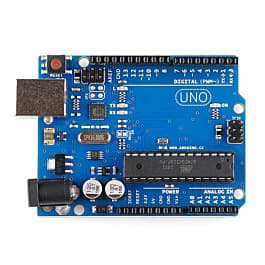
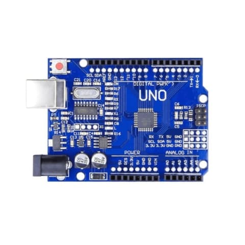
Arduino Uno R3 Development Board (ATmega328P)
Rs 449
Rs 699
 Sale 11%
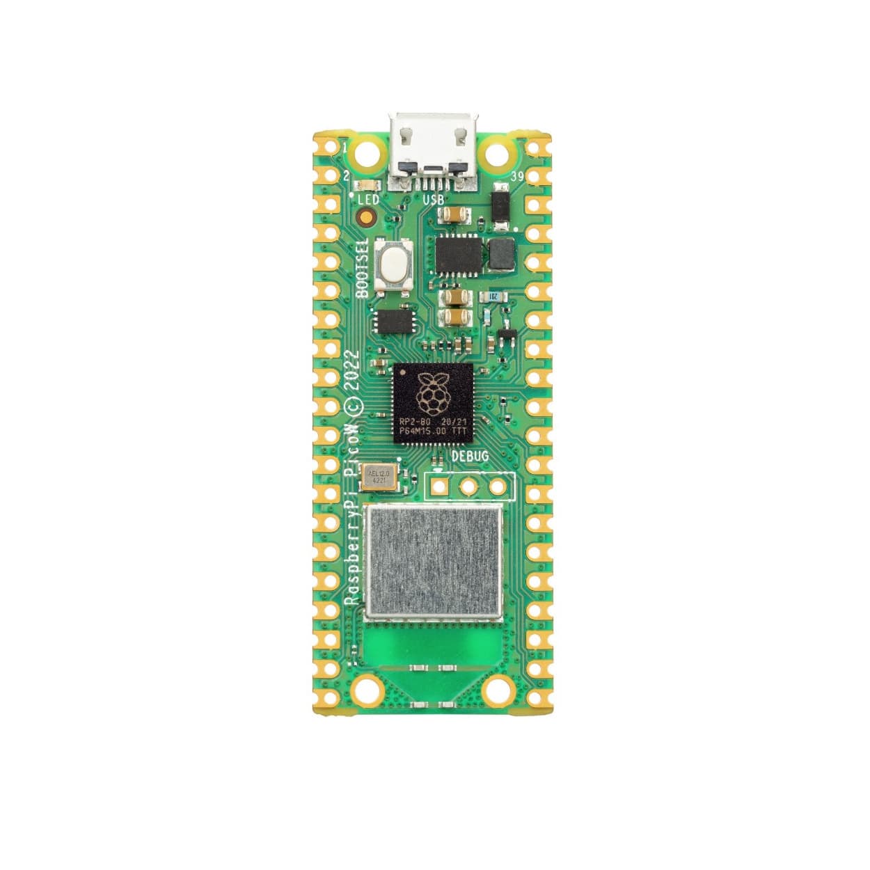
Raspberry Pi Pico W (RP2040 with Wi-Fi & Bluetooth) - Pre-Soldered Headers
Rs 799
Rs 899
 Sale 12%
Raspberry Pi 4 Model B - High-Performance Single Board Computer (2GB / 4GB / 8GB RAM)
Rs 7000
Rs 7999
Arduino UNO SMD CH340 Development Board
Rs 399
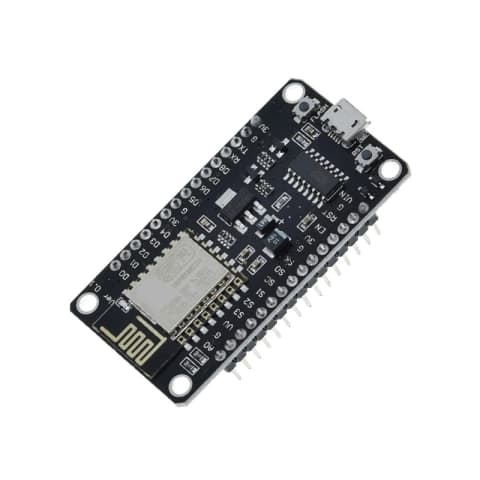
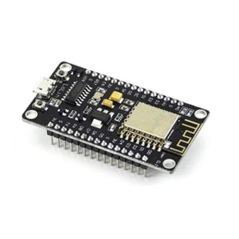
NodeMCU ESP8266 V3 WiFi Development Board (CH340G Driver)
Rs 349
ESP32 30 Pin Standard Development Board
Rs 529
 Sale 18%
Seeed Studio XIAO SAMD21 - Ultra-Small ARM Cortex-M0+ Development Board
Rs 700
Rs 849