1 / 2
1 / 2ESP32-CAM Development Board WiFi+Bluetooth with OV2640 Camera Module (2MP)
Estimated delivery
Sat, 1 Aug
Shipping benefit
Free shipping ₹1,499+*
*Standard delivery; eligible order value applies.
The ESP32-CAM is a highly versatile, ultra-small footprint camera module designed for advanced IoT and machine vision projects. Combining the dual-core processing power of the ESP32-S with a 2-Megapixel OV2640 camera and a built-in MicroSD card slot, this board acts as a standalone wireless computer with eyes. It is perfectly suited for building smart home surveillance cameras, facial recognition systems, QR code scanners, and remote wildlife monitors. With built-in Wi-Fi and Bluetooth, you can easily stream live video or upload captured images directly to the cloud without needing a separate microcontroller.
Secure payments
Expert support
Easy replacements
Everything you need to know
Product details
Bring computer vision to your next hardware project without the high cost of a Raspberry Pi. The ESP32-CAM is a legendary module in the maker community, blending the robust Wi-Fi and Bluetooth capabilities of the ESP32 chip with a high-quality 2MP camera.
Whether you are building a smart doorbell that recognizes faces, an automated robot that tracks objects, or a time-lapse camera for your automated gardening kit, this board handles it all. It features a built-in MicroSD card slot (supporting up to 4GB) so you can store images and data logs locally if your Wi-Fi drops. It also includes an ultra-bright onboard LED flash for low-light environments.
Important Note: To keep the size and cost down, this specific board does not have a built-in USB port. To upload code from the Arduino IDE, you will need an external FTDI USB-to-TTL Programmer or an ESP32-CAM-MB shield.
Key Features
- Processor: Low-power dual-core 32-bit CPU (up to 240MHz, 600 DMIPS computing power).
- Wireless: 802.11b/g/n Wi-Fi and Bluetooth 4.2 (Classic & BLE).
- Camera Included: OV2640 2-Megapixel Camera (UXGA 1600x1200 resolution).
- Memory: Built-in 520 KB SRAM + 4MB external PSRAM (crucial for smooth video buffering).
- Storage: Onboard MicroSD card slot for local image/data storage.
- Flash: High-intensity white LED flash for dark environments.
- Interfaces: Supports UART, SPI, I2C, and PWM.
Pinout Guide (For FTDI Programming)
To put the board into "Flash Mode", you must temporarily connect GPIO 0 to GND while powering it on.
- 5V / 3V3: Power Input (5V highly recommended for stable Wi-Fi/Camera operation).
- GND: Common Ground.
- U0R (RX): Connect to FTDI TX.
- U0T (TX): Connect to FTDI RX.
- IO0 (GPIO 0): Flash Mode Selection (Connect to GND to program, leave open to run).
- IO4: Onboard LED Flash Control.
- IO12, IO13, IO14, IO15: MicroSD Card SPI pins.
Built by the community
Customer reviews
Real builds, honest feedback, and photos from people using ESP32-CAM Development Board WiFi+Bluetooth with OV2640 Camera Module (2MP).
Picked for this product
You might also like
 Sale 9%
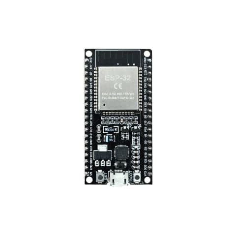
ESP32-WROOM-32 DevKit V1 (Wi-Fi + Bluetooth IoT Board)
Rs 499
Rs 549
 Sale 7%
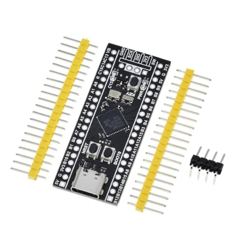
STM32F401CCU6 Black Pill Development Board - High-Performance ARM Cortex-M4
Rs 500
Rs 540
 Sale 11%
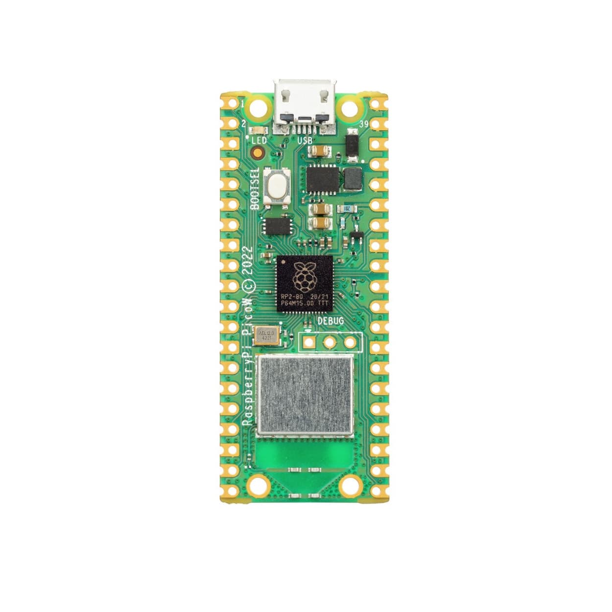
Raspberry Pi Pico W (RP2040 with Wi-Fi & Bluetooth) - Pre-Soldered Headers
Rs 799
Rs 899
ESP32 30 Pin Standard Development Board
Rs 529
 Sale 12%
Raspberry Pi 4 Model B - High-Performance Single Board Computer (2GB / 4GB / 8GB RAM)
Rs 7000
Rs 7999
 Sale 7%
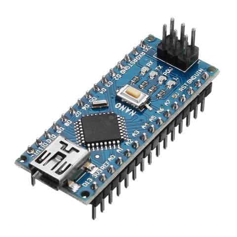
Arduino Nano V3.0 CH340 Development Board (Upgraded Type-C)
Rs 399
Rs 429
 Sale 18%
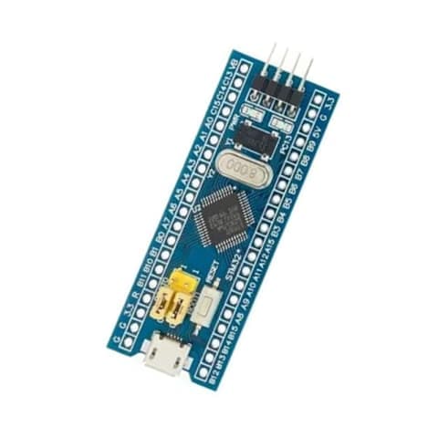
STM32F103C8T6 "Blue Pill" ARM Cortex-M3 Development Board (Seperate Headers)
Rs 249
Rs 302
 Sale 36%
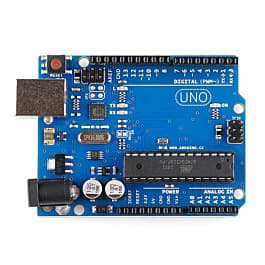
Arduino Uno R3 Development Board (ATmega328P)
Rs 449
Rs 699
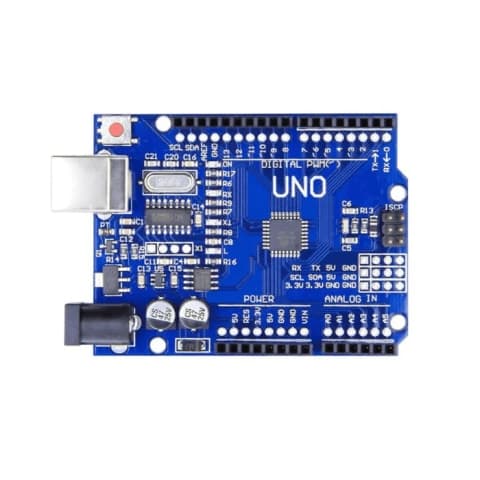
Arduino UNO SMD CH340 Development Board
Rs 399
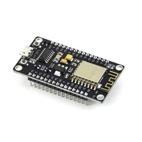
NodeMCU ESP8266 V3 WiFi Development Board (CH340G Driver)
Rs 349