1 / 2
1 / 2TCS3200 Color Recognition Sensor Module with White LEDs
Estimated delivery
Fri, 31 Jul
Shipping benefit
Free shipping ₹1,499+*
*Standard delivery; eligible order value applies.
The TCS3200 is a complete color detector module that uses an array of photodiodes to detect the color of an object. It includes four bright white LEDs to illuminate the target, allowing the sensor to accurately read red, green, blue, and clear light intensities and convert them into a square wave frequency for your microcontroller to process.Key Features:True Color Detection: Senses Red, Green, and Blue (RGB) light levels independently.Integrated Lighting: Features 4 ultra-bright white LEDs to ensure accurate readings regardless of ambient light.Direct Digital Output: Converts light intensity directly into a variable frequency square wave.Wide Compatibility: Easily interfaces with any microcontroller, including Arduino, ESP32, and Raspberry Pi.
Secure payments
Expert support
Easy replacements
Everything you need to know
Product details
Overview
The TCS3200 Color Sensor Module is designed to measure the color of any object placed in front of it. It works by utilizing an 8x8 array of silicon photodiodes—16 have red filters, 16 have green filters, 16 have blue filters, and 16 have no filter (clear).
By using the control pins on the module, you can selectively activate the different color filters. The onboard oscillator then outputs a square wave whose frequency is directly proportional to the intensity of the selected color. This makes it incredibly easy to program color-sorting robots or automated quality-control mechanisms.
Technical Specifications
| Feature | Specification |
|---|---|
| Sensor Chip | TAOS TCS3200 |
| Operating Voltage | 2.7V to 5.5V DC |
| Output Type | Digital Square Wave (Duty cycle 50%) |
| Detection Distance | 10mm to 15mm (Best accuracy) |
| Onboard Illumination | 4x Bright White LEDs |
| Module Dimensions | 28.4mm x 28.4mm |
| Output Frequency Range | Programmable (Typically 10kHz - 12kHz max) |
Pinout Configuration
The module features standard 2.54mm pitch headers, perfectly spaced for jumper wires or breadboard use.
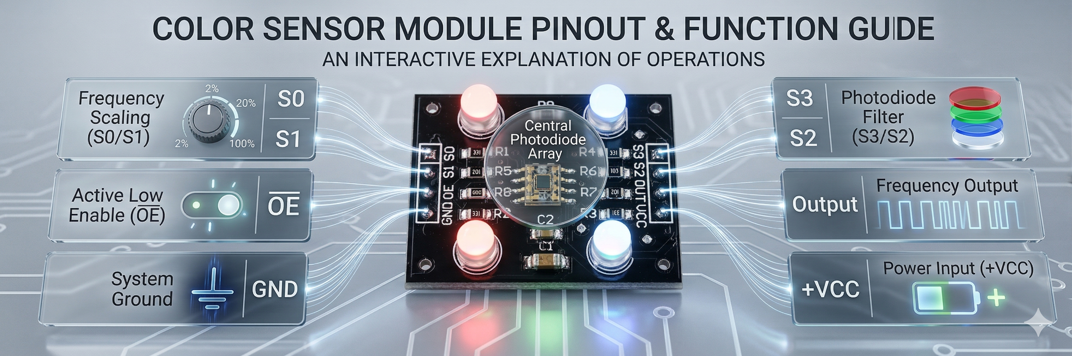
Pin Description
- VCC: Power Supply (3.3V or 5V)
- GND: Ground
- S0 & S1: Output Frequency Scaling selection inputs (scales the output frequency to 2%, 20%, or 100% to match your microcontroller's reading speed).
- S2 & S3: Photodiode Filter selection inputs (used to select whether you are reading Red, Green, Blue, or Clear values).
- OUT: The square wave output pin that goes to your microcontroller's digital input.
- OE / LED: Output Enable (Active Low). On some modules, this pin can also be used to turn the onboard LEDs on and off.
How to Read Colors (Logic Table)
To detect a specific color, you set the S2 and S3 pins to HIGH or LOW logic states:
- RED: S2 = LOW, S3 = LOW
- BLUE: S2 = LOW, S3 = HIGH
- CLEAR (No Filter): S2 = HIGH, S3 = LOW
- GREEN: S2 = HIGH, S3 = HIGH
💡 Pro Tip: To get a highly accurate RGB profile of an object, you must take three separate readings in rapid succession (one for Red, one for Green, and one for Blue) and combine the variables in your code. Ensure ambient lighting is kept as stable as possible for the best results!
Built by the community
Customer reviews
Real builds, honest feedback, and photos from people using TCS3200 Color Recognition Sensor Module with White LEDs.
Picked for this product
You might also like
 Sale 3%
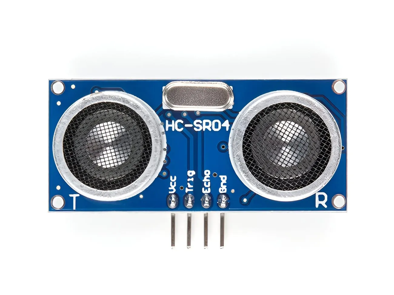
HC-SR04 Ultrasonic Distance Sensor Module
Rs 78
Rs 80
 Sale 13%
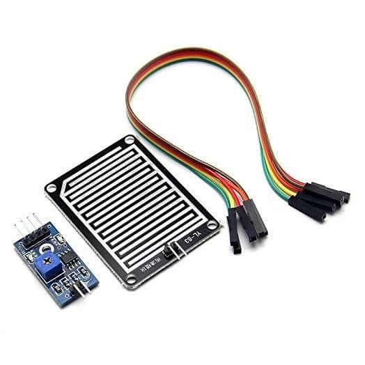
Raindrop Detection Sensor Module | Rain Sensor Module for Arduino
Rs 65
Rs 75
 Sale 7%
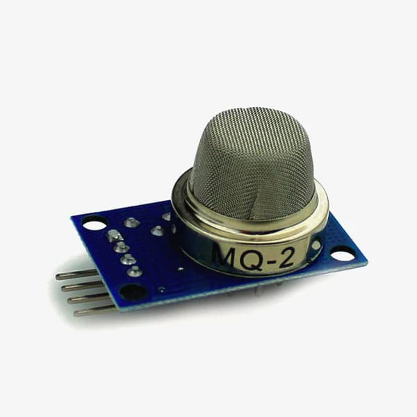
MQ-2 Gas and Smoke Sensor Module
Rs 120
Rs 129
 Sale 18%
IR Infrared Obstacle Avoidance Sensor Module
Rs 45
Rs 55
 Sale 8%
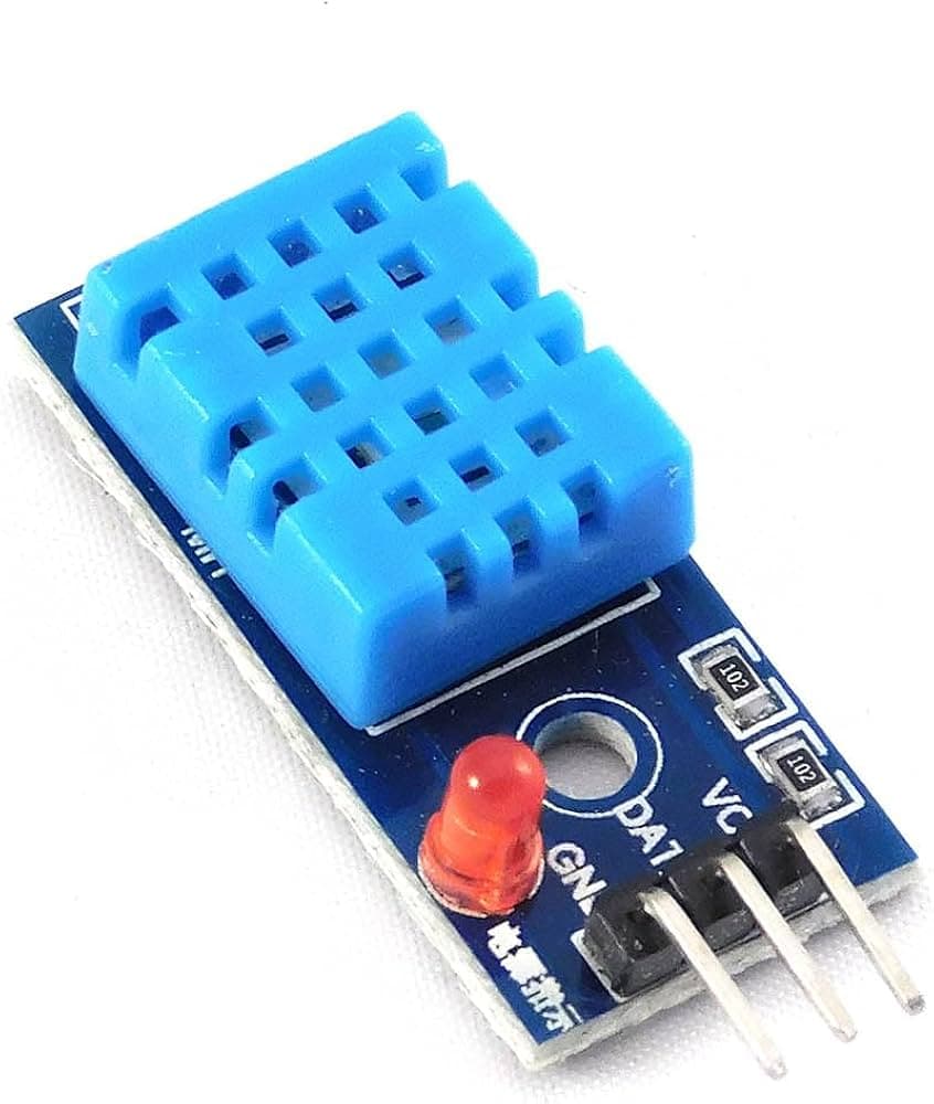
DHT11 Temperature & Humidity Sensor Module
Rs 66
Rs 72
 Sale 3%
MPU6050 6-Axis Accelerometer and Gyroscope Module
Rs 185
Rs 190
 Sale 15%
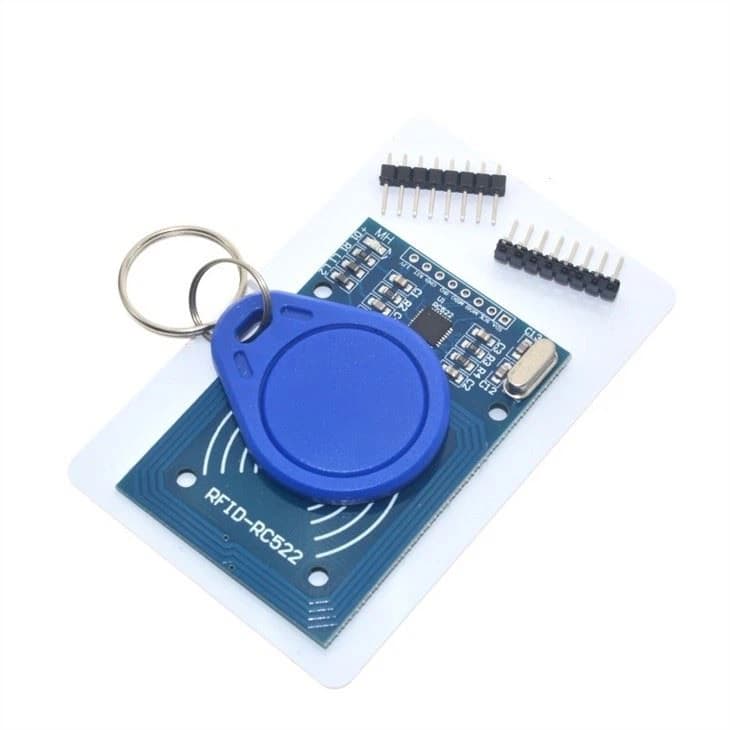
RC522 RFID Reader/Writer Module 13.56MHz (with Card and Keychain)
Rs 169
Rs 199

4x4 Push Button Matrix Keypad
Rs 65

CP2102 USB to TTL Serial Converter
Rs 145
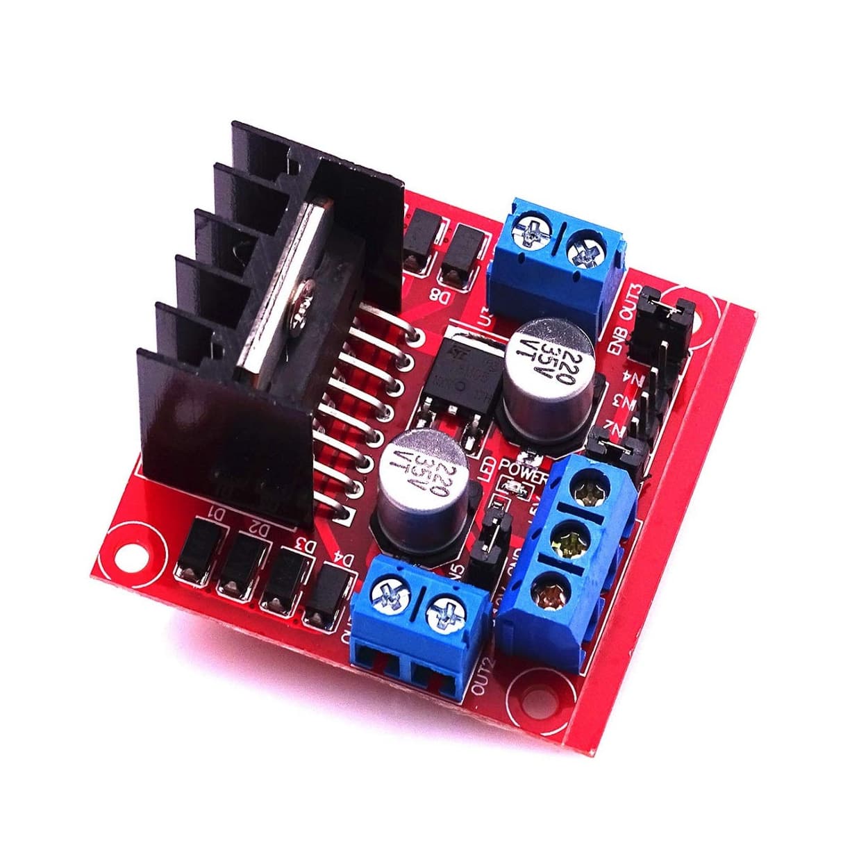
L298N Dual H-Bridge Motor Driver Module
Rs 225