10 Best Beginner Arduino Projects to Master Electronics and Coding
Discover 10 hands-on Arduino projects designed for beginners, complete with component lists, core programming concepts, and practical step-by-step guidance.

Getting Started with Arduino: A Practical Learning Guide
Arduino is an open-source electronics platform based on easy-to-use hardware and software. It serves as an accessible entry point into embedded systems, robotics, and interactive electronics. By combining a physical circuit board (microcontroller) with a simplified C/C++ development environment (the Arduino IDE), makers and engineers can build physical computing devices that sense and respond to the real world.
For a beginner, the primary challenge is rarely abstract theory—it is bridging the gap between schematic diagrams and actual code execution. The most effective way to learn Arduino is through progressive, project-based building.
Essential Starter Hardware
Before diving into individual projects, every beginner should have access to a basic starter hardware kit:
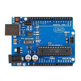
- Microcontroller Board: Arduino Uno R3 or Arduino Uno R4 Minima (the standard benchmark for beginners).
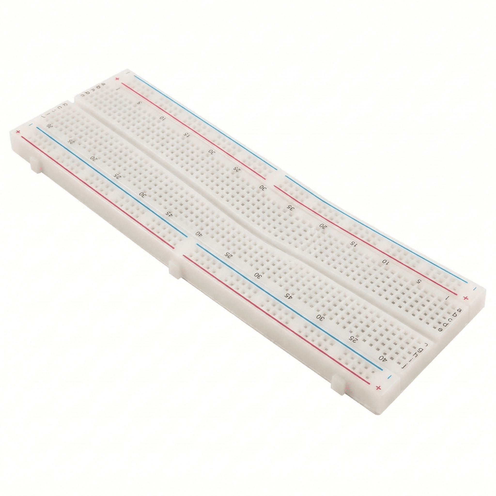
- Solderless Breadboard: Used to assemble circuits without permanent soldering.
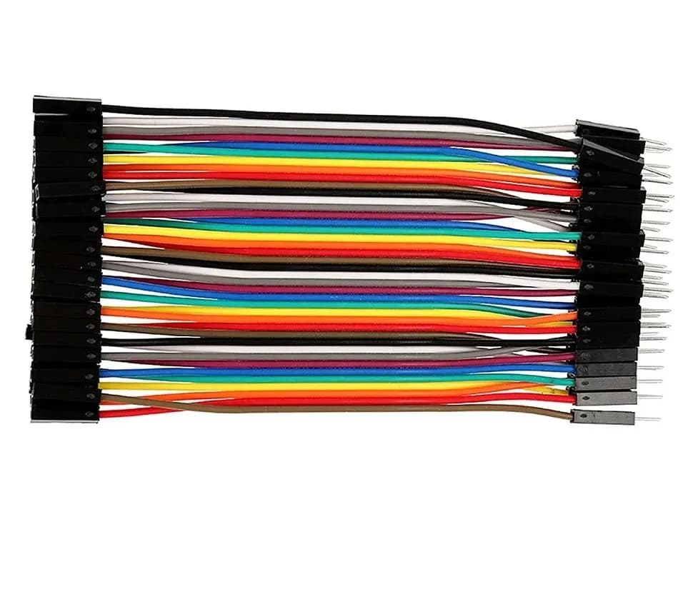
- Jumper Wires: Male-to-Male, Male-to-Female, and Female-to-Female wires for making connections.
- Passives: A selection of resistors (220Ω, 1kΩ, 10kΩ), capacitors, and light-emitting diodes (LEDs).
- Basic Inputs/Outputs: Push buttons, potentiometers, light-dependent resistors (LDRs), and a small piezo buzzer.
- USB Cable: A Type-A to Type-B cable (for classic Uno) to connect the board to your computer for programming and power.
Top 10 Arduino Beginner Projects
The following 10 projects are arranged in order of increasing complexity. Each project introduces a fundamental electronics concept, a distinct programming pattern, and a specific set of hardware components.
1. The Blinking LED (The "Hello World" of Embedded Systems)
Every microcontroller learning journey begins with flashing an LED. This project verifies that your software environment (Arduino IDE), drivers, and board connection are functioning correctly.
- Core Electronics Concept: Current limiting and digital output states.
- Key Software Functions:
pinMode(),digitalWrite(),delay(). - Hardware Needed: Arduino Uno, 1x LED, 1x 220Ω resistor, breadboard, jumper wires.
How It Works
The Arduino sets a digital General Purpose Input/Output (GPIO) pin high (5V) and low (0V) at controlled intervals. The 220Ω resistor protects the LED from drawing excess current and burning out.
// Blinking LED Code Example
const int ledPin = 13; // Built-in LED pin

void setup() {
  pinMode(ledPin, OUTPUT); // Configure digital pin as output
}

void loop() {
  digitalWrite(ledPin, HIGH); // Turn LED on (5V)
  delay(1000);                // Wait for 1 second (1000ms)
  digitalWrite(ledPin, LOW);  // Turn LED off (0V)
  delay(1000);                // Wait for 1 second
}
2. Traffic Light Simulator
Building on the basic LED blink project, the traffic light simulator introduces state sequencing and multi-output management using multiple LEDs.
- Core Electronics Concept: Multi-output timing control.
- Key Software Functions: Sequential function execution, configurable timing variables.
- Hardware Needed: Arduino Uno, 3x LEDs (Red, Yellow, Green), 3x 220Ω resistors, breadboard, jumper wires.
How It Works
Three separate GPIO pins are driven independently to illuminate red, yellow, and green LEDs in a timed sequence that mirrors real-world traffic signals.
const int redPin = 10;
const int yellowPin = 9;
const int greenPin = 8;

void setup() {
  pinMode(redPin, OUTPUT);
  pinMode(yellowPin, OUTPUT);
  pinMode(greenPin, OUTPUT);
}

void loop() {
  // Red phase
  digitalWrite(redPin, HIGH);
  delay(5000);
  digitalWrite(redPin, LOW);

  // Green phase
  digitalWrite(greenPin, HIGH);
  delay(4000);
  digitalWrite(greenPin, LOW);

  // Yellow phase
  digitalWrite(yellowPin, HIGH);
  delay(1500);
  digitalWrite(yellowPin, LOW);
}
3. Push Button LED Toggle with Switch Debouncing
This project introduces physical user input. You will read the state of a switch and toggle an output light. It also introduces "switch bouncing"—a mechanical reality where physical buttons generate noisy voltage spikes when pressed.
- Core Electronics Concept: Digital inputs, pull-down/pull-up resistors, contact bounce.
- Key Software Functions:
digitalRead(), conditional state logic (if...else). - Hardware Needed: Arduino Uno, 1x Push button, 1x 10kΩ pull-down resistor, 1x LED, 1x 220Ω resistor.
How It Works
When the button is open, the pull-down resistor pulls the pin to GND (0V), preventing a floating input state. When pressed, the pin reads HIGH (5V).
const int buttonPin = 2;
const int ledPin = 13;
int buttonState = 0;

void setup() {
  pinMode(buttonPin, INPUT);
  pinMode(ledPin, OUTPUT);
}

void loop() {
  buttonState = digitalRead(buttonPin);

  if (buttonState == HIGH) {
    digitalWrite(ledPin, HIGH);
  } else {
    digitalWrite(ledPin, LOW);
  }
}
4. Light-Sensitive Automatic Night Light (LDR Sensor)
Transitioning from digital (0 or 1) signals to analog signals, this project uses a Light-Dependent Resistor (LDR) to detect ambient light levels and trigger an LED when the room turns dark.
- Core Electronics Concept: Voltage dividers, analog-to-digital conversion (ADC).
- Key Software Functions:
analogRead(), Serial Monitor debugging viaSerial.begin()andSerial.println(). - Hardware Needed: Arduino Uno, 1x LDR (Photoresistor), 1x 10kΩ resistor, 1x LED, 1x 220Ω resistor.
How It Works
The LDR changes resistance based on light exposure. Placed in a voltage divider circuit, it outputs a variable voltage (0–5V) into analog pin A0. The Arduino's internal 10-bit ADC converts this voltage into a digital integer ranging from 0 to 1023.
const int ldrPin = A0;
const int ledPin = 9;
const int threshold = 400; // Adjust based on room ambient light

void setup() {
  Serial.begin(9600);
  pinMode(ledPin, OUTPUT);
}

void loop() {
  int ldrValue = analogRead(ldrPin);
  Serial.print("Current LDR Reading: ");
  Serial.println(ldrValue);

  if (ldrValue < threshold) {
    digitalWrite(ledPin, HIGH); // Dark room: turn on light
  } else {
    digitalWrite(ledPin, LOW);  // Bright room: turn off light
  }
  delay(200);
}
5. Ultrasonic Distance Measurement System
This project introduces range finding using the HC-SR04 ultrasonic sensor. It measures distances using high-frequency sound waves and provides real-time readout data.
- Core Electronics Concept: Ultrasonic flight-time calculation, sensor signal processing.
- Key Software Functions:
pulseIn(), mathematical formulas for physical conversion. - Hardware Needed: Arduino Uno, HC-SR04 ultrasonic sensor, breadboard, jumper wires.
How It Works
The sensor transmits a 40 kHz ultrasonic pulse via its transmitter pin (Trig). The pulse hits an obstacle and bounces back to the receiver pin (Echo). The duration between transmission and reception allows the Arduino to compute the target's distance.
$$\text{Distance (cm)} = \frac{\text{Duration (}\mu\text{s)} \times 0.0343}{2}$$
const int trigPin = 9;
const int echoPin = 10;

void setup() {
  Serial.begin(9600);
  pinMode(trigPin, OUTPUT);
  pinMode(echoPin, INPUT);
}

void loop() {
  digitalWrite(trigPin, LOW);
  delayMicroseconds(2);
  digitalWrite(trigPin, HIGH);
  delayMicroseconds(10);
  digitalWrite(trigPin, LOW);

  long duration = pulseIn(echoPin, HIGH);
  float distanceCm = duration * 0.0343 / 2.0;

  Serial.print("Distance: ");
  Serial.print(distanceCm);
  Serial.println(" cm");
  delay(500);
}
6. Potentiometer-Controlled Servo Motor
Servo motors are essential components in robotics because they allow for precise position control. This project maps analog potentiometer readings to direct motor angular positions.
- Core Electronics Concept: Pulse-Width Modulation (PWM), feedback-driven motor control.
- Key Software Functions:
<Servo.h>library integration,map()utility function. - Hardware Needed: Arduino Uno, 1x Micro Servo (e.g., SG90), 1x 10kΩ potentiometer.
How It Works
Rotating the potentiometer changes the voltage sent to analog pin A0 ($0–1023$). The Arduino maps this input range into degrees ($0^\circ–180^\circ$) and outputs a PWM control signal to position the servo shaft accurately.
#include <Servo.h>

Servo myServo;
const int potPin = A0;

void setup() {
  myServo.attach(9); // Connect servo signal pin to GPIO 9
}

void loop() {
  int potValue = analogRead(potPin);
  // Map analog range (0 to 1023) to Servo angle range (0 to 180)
  int angle = map(potValue, 0, 1023, 0, 180);
  myServo.write(angle);
  delay(15);
}
7. Temperature and Humidity Display with LCD / OLED
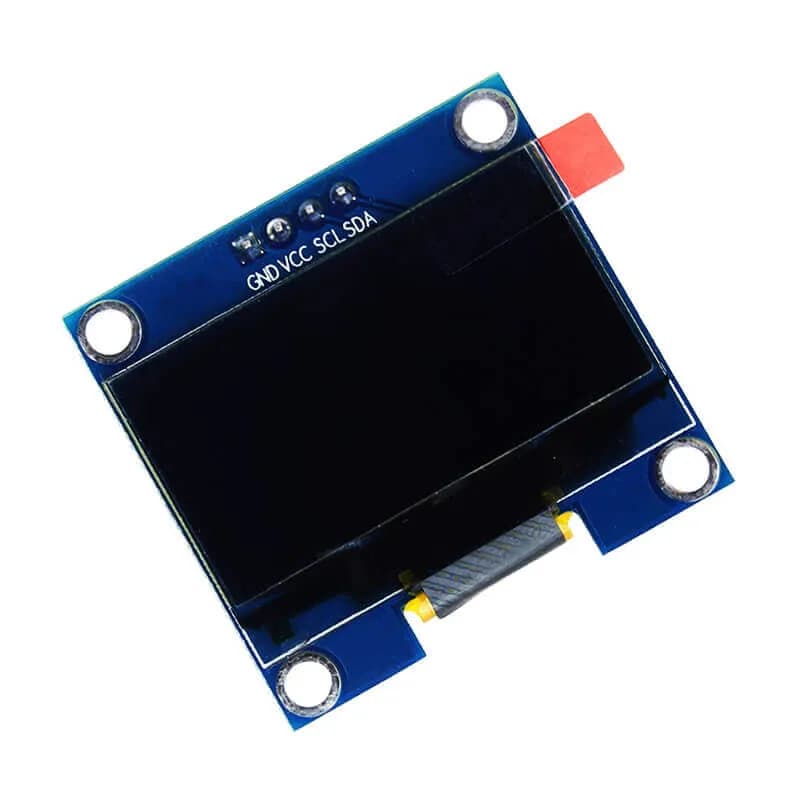
Moving beyond the serial terminal, this project displays environmental readings directly on a 16x2 I2C Liquid Crystal Display (LCD).
- Core Electronics Concept: I2C communication protocol, external digital sensor integration.
- Key Software Functions: Inter-Integrated Circuit (I2C) address communication, library calls (
Wire.h,LiquidCrystal_I2C.h,DHT.h). - Hardware Needed: Arduino Uno, 16x2 I2C LCD Module, DHT11 or DHT22 Temperature/Humidity sensor, breadboard.
How It Works
The DHT sensor delivers a digital bitstream representing relative humidity and temperature. The Arduino decodes this signal and sends display text over the two-wire I2C interface (SDA/SCL lines), minimizing required GPIO pin usage.
8. Soil Moisture Monitoring & Automatic Irrigation Relay
This project introduces high-power load control. It turns dynamic biological inputs into physical automation actions using a mechanical relay switch.
- Core Electronics Concept: Galvanic resistance sensing, high-voltage load switching via relays.
- Safety Note: Keep relay voltage loads within safe DC ranges (5V–12V DC) while learning. Avoid working with mains AC line electricity without advance experience.
- Hardware Needed: Arduino Uno, Capacitive soil moisture sensor, 5V single-channel relay module, small 5V DC water pump or test motor.
How It Works
Soil moisture changes conductivity between probe terminals. When dry soil resistance causes readings to drop below a specified threshold, the Arduino triggers the 5V relay module to power an external pump circuit.
9. IR Remote-Controlled Device Switcher
Infrared (IR) remote communication is standard in consumer electronics. This project decodes signal streams from household IR remotes to turn components on and off.
- Core Electronics Concept: Optical communication protocols (NEC protocol), signal demodulation.
- Key Software Functions: Hexadecimal signal processing, state toggle logic.
- Hardware Needed: Arduino Uno, TSOP1838 IR Receiver module, any standard IR remote control, 2x LEDs with resistors.
How It Works
The TSOP1838 sensor demodulates incoming 38kHz infrared pulses into unique hexadecimal values (e.g., 0xFF30CF). The code checks these decoded hex strings to toggle corresponding GPIO pins.
10. Simple Obstacle-Avoiding Mobile Robot
Combining multiple concepts learned so far—ultrasonic distance sensing, motor direction control, and logic pathways—this project builds an autonomous two-wheeled robot rover.
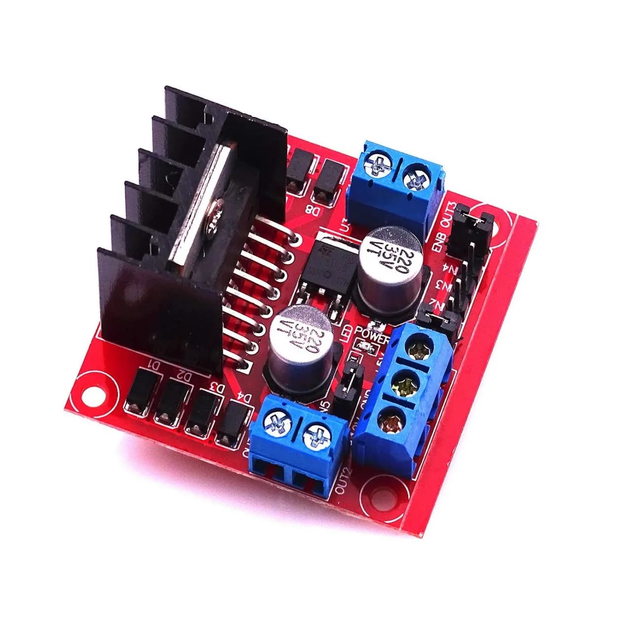
- Core Electronics Concept: H-Bridge motor driving (L298N module), autonomous logic loops, power distribution.
- Key Software Functions: Dual-motor control routines, obstacle-avoidance logic.
- Hardware Needed: Arduino Uno, L298N Dual H-Bridge Motor Driver, 2x DC Gearhead Motors + Wheels, 2-Wheel Robot Chassis, HC-SR04 Sensor, 7.4V–9V Battery Pack.
How It Works
The robot moves forward continuously while checking the ultrasonic sensor. If an obstacle drops below a set threshold (e.g., 20 cm), the Arduino stops both motors, reverses briefly, turns one motor to rotate the chassis, and resumes forward movement.
Arduino Beginner Project Comparison
| Project | Key Skill Learned | Circuit Complexity | Main Programming Concept |
|---|---|---|---|
| 1. Blinking LED | Basic GPIO output | Low | Digital writes & timing delays |
| 2. Traffic Light | Multi-output control | Low | Array-like timing sequences |
| 3. Push Button | Digital input processing | Low-Medium | Pull-down resistors & state checks |
| 4. LDR Night Light | Analog sensor reading | Medium | Voltage dividers & thresholds |
| 5. Distance Sensor | Pulse-timing math | Medium | Time-of-flight physics calculation |
| 6. Servo Potentiometer | PWM output mapping | Medium | Mapping ranges (map()), motor control |
| 7. LCD Temp Display | Bus protocols (I2C) | Medium-High | External libraries & data structures |
| 8. Automated Plant Watering | Relays & power switching | Medium-High | Threshold-based actuator control |
| 9. IR Remote Controller | Signal demodulation | Medium | Hexadecimal protocol parsing |
| 10. Obstacle Robot | System Integration | High | Multi-component logic & motor control |
Critical Safety & Best Practices for Beginners
When starting out with physical electronics, following proper design habits prevents destroyed components, non-responsive boards, or physical hazards:
- Current Protection for LEDs: Never connect an LED directly between 5V and GND. Always place a current-limiting resistor (220Ω to 1kΩ) in series.
- Current Limits on GPIO Pins: Individual Arduino pins can safely source or sink up to 20mA (with an absolute maximum limit of 40mA). Never power high-current loads—such as DC motors, solenoids, or large relays—directly from a GPIO pin. Always use a transistor, MOSFET, or motor driver circuit.
- Common Ground: When using external power supplies for motors or sensors, connect the external power supply ground line directly to the Arduino's
GNDpin. Without a shared common reference ground, digital signals become unstable and unreadable. - Never Wire Powered Circuits: Always disconnect the USB cable and any battery sources before making changes to your physical breadboard connections.
Frequently Asked Questions (FAQ)
Which Arduino board is best for absolute beginners?
The Arduino Uno R3 or Arduino Uno R4 Minima is the ideal choice. Most libraries, tutorials, and beginner hardware shields are designed around the Uno form factor, ensuring maximum hardware and software compatibility.
Do I need prior coding experience to use Arduino?
No. Arduino uses a simplified version of C/C++. The built-in example sketches provided inside the free Arduino IDE allow beginners to start running physical hardware code without prior software architecture experience.
What is the difference between Digital and Analog pins on Arduino?
Digital pins act strictly as binary switches: they output or read either HIGH (5V/3.3V) or LOW (0V). Analog input pins read variable voltages between 0V and 5V, converting them into an internal numerical scale from 0 to 1023 using the built-in Analog-to-Digital Converter (ADC).
Can I power an Arduino project without keeping it connected to a computer?
Yes. Once code is flashed onto the board's flash memory via USB, it stays programmed indefinitely. You can power the board independently using a 9V DC power adapter connected to the barrel jack, or via a battery pack connected to the VIN and GND pins.
Next Steps in Your Hardware Journey
Completing these 10 introductory projects builds a strong foundation in embedded computing, sensor reading, component protection, and actuator control.
Once comfortable with these basics, your next step is exploring advanced platforms:
- Moving from standard microcontrollers to ESP32 platforms to add Wi-Fi and Bluetooth capabilities.
- Integrating advanced motor drivers for precision robotics.
- Deploying remote IoT dashboards to monitor physical environments wirelessly.