Building a Bluetooth Controlled Car: Architecture, Firmware, and Circuit Design
Learn how to build an Arduino-based Bluetooth controlled car from scratch, covering HC-05 level shifting, L298N H-bridge logic, power rail isolation, and C++ firmware architecture.

Building a Bluetooth-controlled car is one of the foundational projects in robotics and embedded engineering. Beyond simple assembly, constructing a reliable mobile robot requires an understanding of digital signal parsing, power decoupling, logic level compatibility, and motor driver physics.
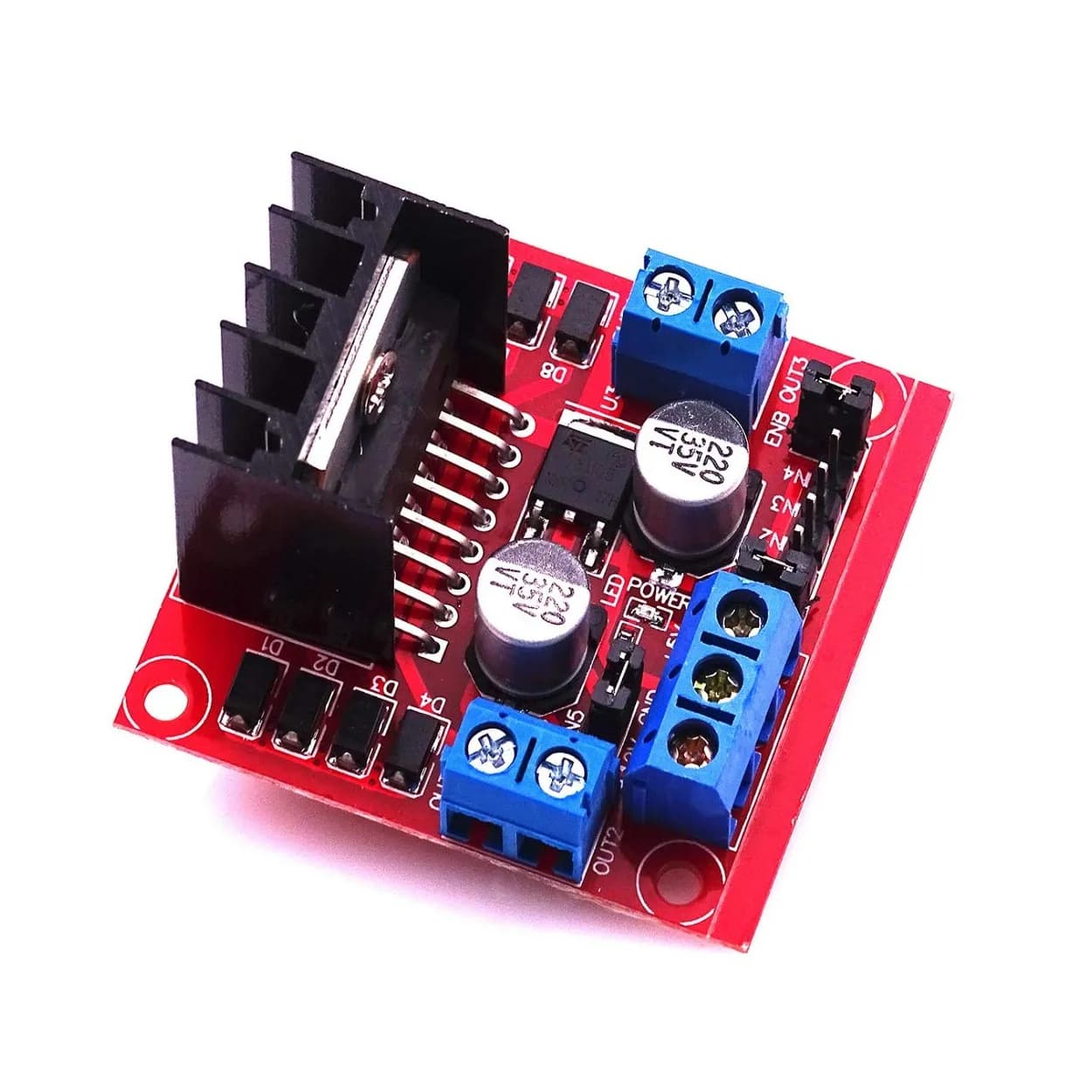
This guide details how to build a four-wheeled (or two-wheeled differential drive) Bluetooth-controlled robot using an Arduino board, an HC-05 Bluetooth module, and an L298N motor driver. The article focuses on hardware selection, electrical isolation, firmware command parsing, and common hardware pitfall remediation.
System Architecture Overview
A Bluetooth-controlled car converts wireless radio frequency signals into physical motion using a layered control pipeline:
- User Interface (Control Source): A smartphone application transmits control codes (ASCII bytes) over Bluetooth Classic using the Serial Port Profile (SPP).
- Wireless Transceiver (HC-05): Receives the RF signal and forwards the data as standard asynchronous serial UART packets (TX/RX).
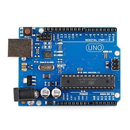
- Microcontroller (Arduino Uno): Parses incoming UART packets, executes control state logic, and generates corresponding Digital and PWM (Pulse-Width Modulation) signals.
- Motor Driver (L298N H-Bridge): Takes logic-level control signals from the microcontroller and switches high-current DC power to the drive motors.
- Actuators (DC Gear Motors): Convert electrical energy into rotational kinetic force to drive the wheels.
[ Smartphone App ] --(Bluetooth SPP)--> [ HC-05 Transceiver ]
                                                |
                                           (UART RX/TX)
                                                v
[ Power Supply ] ---> [ Motor Driver ] <--- [ Arduino Uno ]
                             |
                      (PWM / Direction)
                             v
                       [ DC Motors ]
Required Components and Hardware Specifications
To build a reliable system that resists electrical interference and voltage drops, select components matching these parameters:
| Component | Function / Role | Key Specification |
|---|---|---|
| Arduino Uno / Nano | Main Processor | ATmega328P, 5V Logic, Hardware/Software UART |
| HC-05 Bluetooth Module | Wireless Serial Receiver | Bluetooth 2.0+EDR, SPP Support, 3.3V Logic RX |
| L298N Driver Module | Dual H-Bridge Motor Controller | Peak current 2A per channel, 5V-35V motor rail |
| DC Motors (2x or 4x) | Propulsion | Yellow TT Gear Motors (3V–6V DC, ~200 RPM) |
| Power Source | System Power | 2x 18650 Li-ion cells (7.4V nominal) or 6x AA batteries |
| Resistors (for divider) | Logic Level Shifting | 1kΩ and 2kΩ (or 2.2kΩ) 1/4W resistors |
| Chassis Kit | Mechanical Frame | Acrylic/Aluminum 2WD or 4WD chassis with wheels |
Circuit Electronics and Wiring Logic
Connecting low-voltage processing logic directly to high-current inductive motor loads can lead to system instability, microcontroller brownouts, or permanent component damage. Follow these hardware principles during assembly.
1. Bluetooth Module (HC-05) Signal Conditioning
The HC-05 operates on a 5V power supply, but its communication logic lines use 3.3V levels. While the HC-05 TX pin safely drives the Arduino digital RX pin directly (3.3V meets the high threshold for 5V TTL), the Arduino 5V TX output can degrade or burn out the HC-05 RX pin over time.
Use a simple voltage divider on the Arduino TX line feeding the HC-05 RX line:
$$V_{out} = V_{in} \times \left( \frac{R_2}{R_1 + R_2} \right) = 5\text{V} \times \left( \frac{2000}{1000 + 2000} \right) \approx 3.33\text{V}$$
- Arduino TX (Pin 2 / SoftwareSerial) $\rightarrow$ $1\text{k}\Omega$ resistor $\rightarrow$ HC-05 RX
- HC-05 RX $\rightarrow$ $2\text{k}\Omega$ resistor $\rightarrow$ GND
2. Motor Driver Logic (L298N Configuration)
The L298N features two full H-bridge circuits. Each bridge uses two directional control inputs (IN1/IN2 for Motor A, IN3/IN4 for Motor B) and an Enable pin (ENA and ENB).
- Directional Control: Setting
IN1HIGH andIN2LOW drives Motor A forward. Reversing the pins (IN1LOW,IN2HIGH) reverses motor polarity. - Speed Control: Removing the jumper caps on
ENAandENBallows PWM signal injection from Arduino analog pins (e.g., Pin 5 and Pin 6). Adjusting the duty cycle controls motor speed.
3. Power Distribution and Common Ground
Inductive spike loads caused by starting and stopping DC motors cause voltage sag on power lines.
- Separate Power Rails: Route motor power directly from the 7.4V battery pack to the L298N power terminal block (
VMS/12V). - 5V Logic Power: You can power the Arduino through its
VINpin using the 7.4V pack, or power it via the 5V regulated output pin of the L298N if its internal 7805 regulator jumper is active. - Common Ground (Crucial): All components—Arduino, HC-05, L298N, and Battery—must share a unified Ground (GND) connection. Without a common signal reference, UART communication and logic switching will fail randomly.
Circuit Connection Matrix
| Arduino Pin | Connected Module | Module Pin | Signal Purpose |
|---|---|---|---|
| Pin 2 | HC-05 Transceiver | TXD | SoftwareSerial RX (Receives from BT) |
| Pin 3 | HC-05 Transceiver | RXD (via Divider) | SoftwareSerial TX (Sends to BT) |
| Pin 5 (PWM) | L298N Driver | ENA | Left Motor Speed Control |
| Pin 6 (PWM) | L298N Driver | ENB | Right Motor Speed Control |
| Pin 7 | L298N Driver | IN1 | Left Motor Direction A |
| Pin 8 | L298N Driver | IN2 | Left Motor Direction B |
| Pin 9 | L298N Driver | IN3 | Right Motor Direction A |
| Pin 10 | L298N Driver | IN4 | Right Motor Direction B |
| 5V | HC-05 Transceiver | VCC | 5V Module Power |
| GND | System Bus | Common GND | Universal Signal Reference |
Note: SoftwareSerial is recommended on digital pins 2 and 3 during prototyping so that hardware pins 0 (RX) and 1 (TX) remain open for USB code uploading and Serial Monitor debugging.
Controller Firmware Implementation
The firmware runs an execution loop that continuously polls the serial buffer for incoming command characters, updates motor driver control states, and handles speed modulation.
#include <SoftwareSerial.h>

// Define SoftwareSerial pins (RX, TX)
SoftwareSerial bluetooth(2, 3);

// L298N Pin Definitions
const int ENA = 5;  // PWM Left
const int ENB = 6;  // PWM Right
const int IN1 = 7;  // Left Forward
const int IN2 = 8;  // Left Reverse
const int IN3 = 9;  // Right Forward
const int IN4 = 10; // Right Reverse

// Default state variables
int motorSpeed = 200; // Speed range: 0 - 255
char command = 'S';   // Current command state

void setup() {
  // Configure motor driver logic output pins
  pinMode(ENA, OUTPUT);
  pinMode(ENB, OUTPUT);
  pinMode(IN1, OUTPUT);
  pinMode(IN2, OUTPUT);
  pinMode(IN3, OUTPUT);
  pinMode(IN4, OUTPUT);

  // Initialize motor state to OFF
  stopMotors();

  // Set baud rate for Software Serial (HC-05 default is typically 9600)
  bluetooth.begin(9600);
}

void loop() {
  // Read incoming serial commands non-blockingly
  if (bluetooth.available() > 0) {
    command = bluetooth.read();
    processCommand(command);
  }
}

void processCommand(char cmd) {
  switch (cmd) {
    case 'F':
      moveForward();
      break;
    case 'B':
      moveBackward();
      break;
    case 'L':
      turnLeft();
      break;
    case 'R':
      turnRight();
      break;
    case 'S':
      stopMotors();
      break;
    // Speed parsing (0 = minimum, 9 = max PWM)
    case '0' ... '9':
      motorSpeed = map(cmd - '0', 0, 9, 0, 255);
      updateSpeed();
      break;
    default:
      // Unknown command: halt for safety
      stopMotors();
      break;
  }
}

void moveForward() {
  updateSpeed();
  digitalWrite(IN1, HIGH);
  digitalWrite(IN2, LOW);
  digitalWrite(IN3, HIGH);
  digitalWrite(IN4, LOW);
}

void moveBackward() {
  updateSpeed();
  digitalWrite(IN1, LOW);
  digitalWrite(IN2, HIGH);
  digitalWrite(IN3, LOW);
  digitalWrite(IN4, HIGH);
}

void turnLeft() {
  updateSpeed();
  // Skid steering: Left wheels reverse, Right wheels forward
  digitalWrite(IN1, LOW);
  digitalWrite(IN2, HIGH);
  digitalWrite(IN3, HIGH);
  digitalWrite(IN4, LOW);
}

void turnRight() {
  updateSpeed();
  // Skid steering: Left wheels forward, Right wheels reverse
  digitalWrite(IN1, HIGH);
  digitalWrite(IN2, LOW);
  digitalWrite(IN3, LOW);
  digitalWrite(IN4, HIGH);
}

void stopMotors() {
  analogWrite(ENA, 0);
  analogWrite(ENB, 0);
  digitalWrite(IN1, LOW);
  digitalWrite(IN2, LOW);
  digitalWrite(IN3, LOW);
  digitalWrite(IN4, LOW);
}

void updateSpeed() {
  analogWrite(ENA, motorSpeed);
  analogWrite(ENB, motorSpeed);
}
Code Logic and Architecture Highlights
- Non-Blocking Serial Reading: The control code uses
bluetooth.available()checks insideloop()without using hardware-stallingdelay()functions. This keeps the execution loop responsive to rapid incoming state changes. - Speed Scaling: Using ASCII characters
'0'through'9', themap()function converts decimal indices to standard 8-bit PWM duty cycles ($0\text{--}255$), corresponding to output voltages across the motors. - Differential Skid Steering: To make a tight turn without a dedicated steering servo, the vehicle rotates the left side and right side motor sets in opposite directions.
Smartphone Controller Configuration
To issue commands to your vehicle:
- Download a generic Bluetooth Serial Controller application from your mobile app store (e.g., Serial Bluetooth Terminal for Android or iOS equivalents).
- Pair your mobile phone with the HC-05 module in your system settings (Default PIN code is typically
1234or0000). - Inside the mobile application, connect to the HC-05 terminal device.
- Set up touch buttons or directional pads to transmit corresponding ASCII characters over Serial:
- Up Button: Transmit byte
'F'on press,'S'on release. - Down Button: Transmit byte
'B'on press,'S'on release. - Left Button: Transmit byte
'L'on press,'S'on release. - Right Button: Transmit byte
'R'on press,'S'on release.
- Up Button: Transmit byte
Common Debugging Scenarios and Pitfalls
Issue 1: Microcontroller Resets When Motors Start
- Symptom: The Bluetooth connection drops and the Arduino status LED reboots whenever a movement command is sent.
- Root Cause: Inrush current drawn by DC motors causes a localized voltage collapse on the battery bus, triggering the microcontroller's Brown-Out Detection (BOD).
- Fix:
- Ensure you are not running the motors directly off a 9V transistor battery or the Arduino's 5V pin. Use high-discharge rate batteries like 18650 Li-ion cells.
- Add a $100\mu\text{F}$ to $470\mu\text{F}$ electrolytic capacitor across the main power terminal inputs of the L298N driver module to smooth out current surges.
Issue 2: Code Fails to Upload to Arduino
- Symptom: Arduino IDE returns an
avrdude: stk500_getsync()sync error during code upload. - Root Cause: If you wired the HC-05 module directly to hardware Serial pins
0 (RX)and1 (TX)instead of usingSoftwareSerial, the Bluetooth module interferes with USB bootloader communications. - Fix: Unplug the RX/TX jump wires from the HC-05 while uploading code, or switch to the
SoftwareSerialconfiguration outlined in the wiring section above.
Issue 3: Wheels Spin in Reverse or Inconsistently
- Symptom: Sending the
'F'command causes the left wheels to turn forward and right wheels to turn backward. - Root Cause: Direct Current motor leads are wired with inverted polarity relative to the L298N pin setup.
- Fix: Swap the physical terminal connection wires for the misbehaving motor channel at the L298N block terminal, or invert the corresponding logic output states (
IN3/IN4) inside your software logic.
Frequently Asked Questions
Can I use an HC-06 module instead of an HC-05?
Yes. The HC-06 functions identically for this project as a Bluetooth slave device. The primary difference is that the HC-05 can act as both a Master and Slave device, whereas the HC-06 operates only as a Slave. Wiring and serial logic remain unchanged.
What is the advantage of an L298N over an L293D shield?
The L298N features larger heat sinks, lower thermal throttling, and handles higher current loads (up to 2A per channel versus 600mA on the L293D). This makes the L298N far better suited for multi-motor 4WD robot platforms.
How do I increase the operational range of the Bluetooth car?
Standard Bluetooth Class 2 modules like the HC-05 have an operational line-of-sight range of roughly 10 meters (33 feet). For higher control distances, replace the Bluetooth module with an ESP32 for Wi-Fi/UDP control or an NRF24L01 2.4GHz RF transceiver system.
Next Steps for Advanced Development
Once your basic movement logic is stable, consider implementing these additional embedded systems improvements:
- Watchdog Timers / Safety Timeout: Add a timer loop inside the firmware to automatically halt the vehicle (
stopMotors()) if no command byte is received within 500 milliseconds, preventing runaways when Bluetooth disconnects. - Speed Ramp Profiling: Instead of instantly switching PWM duty cycle output, write a dynamic ramp-up routine to smooth mechanical acceleration and reduce mechanical strain on gearbox teeth.
- Sensor Integration: Interface HC-SR04 Ultrasonic Distance Sensors to create an automated emergency braking system (AEB) when obstacles approach within 15 cm.