Designing and Building a Custom Mobile Robot Chassis: An Engineering Guide
Learn how to choose drive kinematics, select chassis materials, manage weight distribution, and build a rigid mobile robot chassis for custom robotics projects.

Introduction to Mobile Robot Chassis Design
Every mobile robot relies on its chassis as its foundational structural backbone. While beginners often start with pre-assembled plastic kits, moving to intermediate robotics requires designing or building custom frames tailored to specific motors, sensors, power distribution systems, and operational environments.
A well-engineered robot chassis does more than hold components together—it preserves wheel alignment, mitigates vibration transferred to sensitive sensors like inertial measurement units (IMUs), manages structural stress, and optimizes weight distribution for maximum traction and efficiency. This guide covers the mechanics, materials, kinematics, and assembly techniques necessary to construct a custom chassis for mobile robots.
Selecting the Right Drive Kinematics
Before cutting materials or printing parts, you must select a motor and wheel arrangement (drive kinematics). The kinematic model dictates how your chassis moves, how many gearmotors you need, and how chassis loads are distributed.
Differential Drive (2WD with Caster)
A two-wheel drive (2WD) differential chassis uses two independently powered drive wheels on a single transverse axis, supplemented by one or two omnidirectional caster wheels for dynamic balance.
- Advantages: Simple drive control, tight zero-radius turning, minimal mechanical drag.
- Limitations: Poor traction on rough or uneven terrain; sensitive to weight distribution over the caster.
4-Wheel Drive (4WD Skid-Steer)
A four-wheel drive chassis powers four wheels directly or via belts/chains. Steering is accomplished by running the left and right wheel pairs at different speeds, sliding (skidding) the tires during turns.
- Advantages: Excellent traction on carpets, grass, and outdoor surfaces; high load capacity.
- Limitations: Higher energy consumption during turns due to lateral tire scrub; increased strain on motor shafts and gearboxes.
Tracked / Tank Drive
Tracked vehicles wrap continuous treads over multiple rollers driven by gearmotors.
- Advantages: Superior ground contact area, ideal for mud, sand, and severe obstacles.
- Limitations: Low efficiency on smooth surfaces, higher friction loss, complex tensioning mechanics.
Kinematics Comparison
| Drive Configuration | Steering Mechanism | Terrain Capability | Structural Complexity | Power Efficiency |
|---|---|---|---|---|
| 2WD + Caster | Differential | Indoor / Smooth | Low | High |
| 4WD Skid-Steer | Skid-Steer | Mixed / Moderate | Medium | Moderate |
| Tracked Drive | Skid-Steer | Rugged / Outdoor | High | Low |
| Ackermann (Car-like) | Front Servo Linkage | Flat / High-Speed | High | High |
Choosing Base Plate Materials
The structural material of your chassis determines its rigidity, weight, resonant frequency, and ease of modification.
+-------------------------------------------------------+
|                 Top Deck: Sensor Rig                  |
|          (LiDAR, Camera, IMU, Microcontroller)        |
+-------------------------------------------------------+
                           || Standoffs
+-------------------------------------------------------+
|               Bottom Deck: Power & Drive              |
|         (Batteries, Motor Drivers, Gearmotors)        |
+-------------------------------------------------------+
Acrylic (PMMA)
Acrylic sheet is a common prototyping material because it is easy to laser-cut and visually transparent. However, acrylic is brittle. Under dynamic mechanical shocks or over-tightened fasteners, it easily cracks along stress concentration points such as sharp internal corners or drill holes.
Aluminum Alloy (6061-T6 / 5052)
Aluminum offers an exceptional strength-to-weight ratio and natural thermal dissipation, making it ideal for motor mounts and structural decks. Sheets between 1.5 mm and 3.0 mm thickness provide high torsional stiffness without adding unnecessary mass. Drilling and bending require metalworking tools, but aluminum resists impact damage that would fracture plastic.
3D Printed Polymers (PLA, PETG, ABS)
3D printing allows custom component geometry, integrated motor brackets, cable routing channels, and recessed mounting holes.
- PLA: Easy to print and stiff, but brittle under impact and softens at temperatures above 50°C (near hot gearmotors).
- PETG: Excellent impact strength, chemical resistance, and thermal tolerance. Preferred for load-bearing brackets.
- ABS/ASA: Tough and lightweight, but requires a heated enclosure to prevent warping during printing.
Medium-Density Fiberboard (MDF) & Plywood
Hardwood plywood or high-density fiberboard (3 mm to 6 mm) is an inexpensive material for physical mockups. While easy to machine with basic hand tools, wood absorbs atmospheric humidity over time, which can warp alignment axes.
Essential Mechanical Principles for Chassis Stability
Constructing a reliable chassis requires planning beyond cutting a single sheet of material. Pay close attention to these critical mechanical factors:
Center of Gravity (CoG) & Traction
The center of gravity (CoG) directly impacts drive traction and balance:
- 2WD Chassis: Keep the CoG positioned slightly forward of the main drive axle toward the caster. If the CoG is located behind the drive axle, the front of the robot will lift during forward acceleration. If the CoG rests entirely on the caster wheel, drive wheels slip due to reduced normal force ($F_N$).
- 4WD Skid-Steer: Center the CoG symmetrically between front and rear axles to ensure uniform tire friction on both sides during turns.
Structural Stiffness & Frame Flex
If a chassis flexes excessively under payload, motor shafts misalign, increasing gear wear and causing erratic encoder readings. To mitigate flex:
- Use a multi-deck (sandwich) architecture supported by metallic standoffs.
- Add vertical stiffening ribs or flange bends along long flat plates.
- Avoid large unsupported spans between motor mounts.
Motor Shaft Load Management
Directly mounting a wide wheel onto a small gearmotor shaft creates a cantilevered load. Over time, side impacts against the wheel exert severe bending moments on the output shaft, destroying internal plastic or brass gear teeth.
Always support drive axles using secondary pillow-block bearings or dedicated bearing mounts when using heavy wheels or carrying payloads exceeding 3 kg.
Step-by-Step Guide: Assembling a Dual-Deck 2WD Mobile Chassis
This step-by-step procedure outlines how to construct a dual-deck differential drive chassis designed for intermediate-level navigation projects.
Required Materials & Hardware
- Chassis Base Decks: 2x Cut plates (2.0 mm Aluminum or 4.0 mm PETG / Birch Plywood)
- Motors: 2x DC Gearmotors with integrated quadrature encoders
- Mounting Brackets: 2x Stamped steel or 3D-printed aluminum motor brackets
- Wheels: 2x Rubber tires (65–80 mm diameter) with matching shaft hubs
- Caster: 1x Steel ball caster or nylon omni-directional wheel (height-matched)
- Hardware: Brass M3 standoffs (35 mm height), M3 machine screws, locknuts, rubber vibration dampers
- Tools: Hex key set, small spanner, drill, threadlocker compound
Assembly Steps
Step 1: Layout Drafting and Marking
Draw or print a 1:1 scale drilling template. Mark mounting points for motor brackets, vertical frame standoffs, battery holders, and central wire feed-through cutouts. Maintain symmetry along the central longitudinal axis.
Step 2: Motor and Bracket Attachment
Secure the gearmotor brackets to the bottom face of the lower deck using M3 machine screws and nylon-insert locknuts.
  [Deck Plate]
-------|-----------------------
       |  <-- M3 Machine Screw
   [Motor Bracket]
       |
   [Gearmotor] ==== (Output Shaft)
Apply a drop of medium-strength threadlocker to all metal-on-metal threaded joints to prevent hardware from loosening due to motor vibration.
Step 3: Wheel Hub Mounting
Press-fit or set-screw the aluminum shaft hubs onto the gearmotor output shafts. Align set-screws with the flat side ("D-flat") of the motor shaft. Mount the main rubber tires onto the hubs and verify that the wheels rotate smoothly without rubbing against the chassis edge.
Step 4: Installing the Balance Caster
Mount the rear/front ball caster to the lower deck using spacer washers to ensure the lower plate sits parallel to the ground. Verify ground clearance—aim for 10 mm to 20 mm clearance to navigate small bumps, thresholds, or thick carpet.
Step 5: Lower Deck Components & Power
Mount heavy components on the bottom deck to keep the center of gravity low:
- Place the main battery pack low and centered directly over or near the main drive axis.
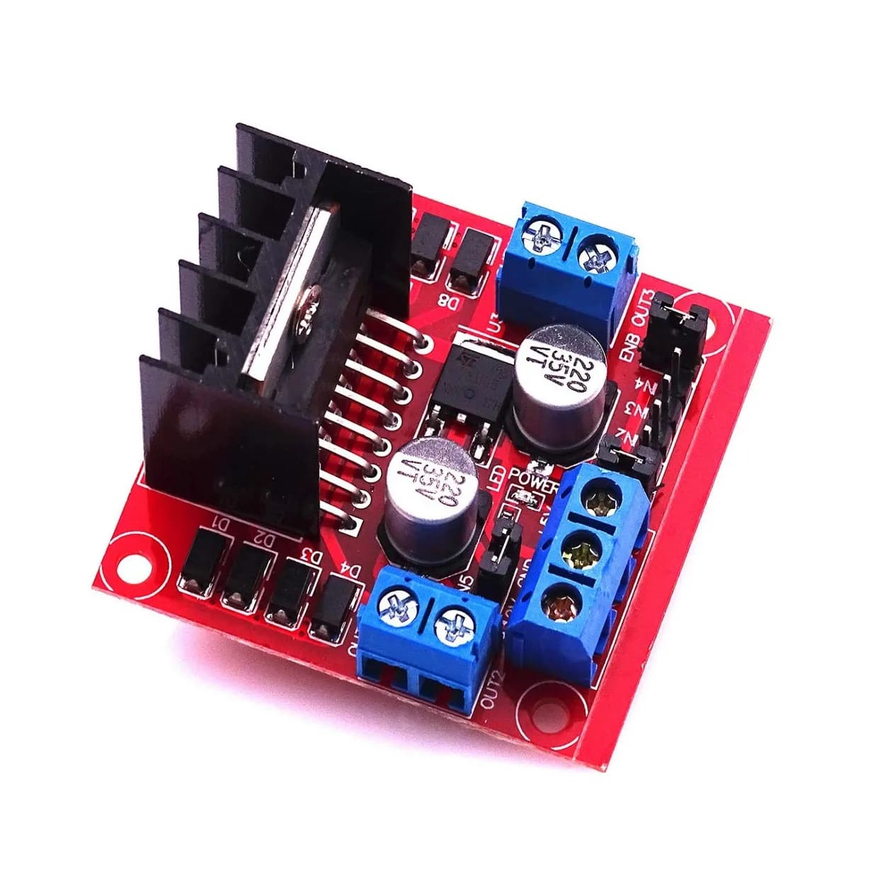
- Secure the dual motor driver module adjacent to the motors using M3 nylon standoffs to isolate the PCB electrically.
Step 6: Installing Upper Deck Standoffs and Top Deck
Thread four to six 35 mm brass standoffs onto the top side of the bottom deck. Route motor power wires and encoder lines through central chassis cutouts. Lower the top deck onto the standoffs and lock it into place with M3 screws. Mount high-level electronics (microcontrollers, single-board computers, IMU modules) on the top deck.
Common Mistakes to Avoid
- Rigidly Mounting Vibration-Sensitive Sensors: Fastening an IMU or gyro sensor directly to an un-damped acrylic or metal plate near gearboxes introduces high-frequency vibration noise into accelerometer telemetry. Use soft silicone vibration isolators or foam tape under IMU break-out boards.
- Ignoring Cable Strain Relief: Connecting moving or exposed wiring directly to screw terminals without zip-tie anchors leads to fatigue failure or sudden disconnection during sharp turns.
- Underestimating Wheel Scrub Friction: Using wide, high-grip rubber tires on a long 4WD skid-steer frame prevents smooth turning. Keep the ratio of track width (distance between left and right wheels) larger than the wheelbase length (distance between front and rear axles) for skid-steer layouts.
- Incorrect Fastener Selection: Relying on basic friction screws into raw plastics without lock washers or threadlockers cause chassis hardware to work loose during operation.
Frequently Asked Questions
What thickness plate should I use for a small to mid-sized robot?
For small indoor mobile robots weighing under 3 kg, 2.0 mm aluminum, 3.0 mm PETG/ABS, or 4.0 mm wood plywood provides sufficient flexural strength. For heavier payloads (5 kg to 15 kg), use 3.0 mm aluminum plates stiffened with vertical corner posts.
Should I choose a single ball caster or a dual caster setup?
A single ball caster (forming a 3-point contact tripod layout) guarantees that all three ground contact points touch the floor regardless of surface imperfections. Using two casters can cause the chassis to rock on uneven floors, temporarily lifting one of the main drive wheels off the ground and losing directional tracking.
How do I prevent motor shaft damage during side impacts?
Install external bearing blocks (pillow blocks) to support the outer edge of the wheel axle. This transfers radial impact loads directly into the chassis plate rather than into the gearmotor’s internal brass bushings and gearbox.
Next Steps
Once your physical chassis is fully assembled and mechanically aligned:
- Perform a manual wheel alignment check to ensure both drive wheels run completely parallel.
- Install optical or magnetic encoders on both motor output shafts to collect wheel odometry.
- Connect motor drivers and run basic calibration scripts to balance power delivery across both motors.
- Add secondary upper decks for modular expansion, such as camera mounts, robotic arms, or depth scanners.