How to Build a Line-Following Robot: From Circuits to PID Control
Learn how to build and tune an autonomous line-following robot using an Arduino, IR sensor arrays, motor drivers, and PID control algorithms for smooth navigation.

Line-following robots are among the foundational projects in mobile robotics. They integrate electro-optical sensing, embedded software, power management, and closed-loop motor control into a single autonomous system.
While a basic line follower uses simple on-off (bang-bang) control with two sensors, an intermediate-level robot requires smoother tracking, higher speeds, and the ability to handle sharp turns or track gaps. Achieving high performance requires an array of infrared (IR) sensors paired with a Proportional-Integral-Derivative (PID) control algorithm running on a microcontroller.
This guide details how to build, wire, code, and tune an autonomous line-following robot using an Arduino micro-controller board, an IR sensor array, and differential drive steering.
Core System Architecture
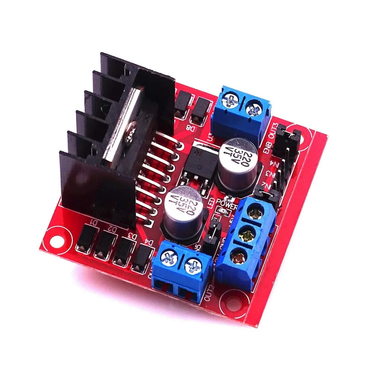
A line-following robot operates as a feedback loop. Optical sensors continuously read light reflectivity from the floor, convert these signals into track position data, and send them to the microcontroller. The controller calculates motor speed corrections and drives the motors through a dual H-bridge motor driver.
+------------------+     Analog/Digital     +------------------+
| IR Sensor Array  | ---------------------> |  Microcontroller |
| (5-Channel TRT)  |                        |  (e.g., Arduino) |
+------------------+                        +------------------+
                                                     |
                                            PWM Motor Signals
                                                     v
+------------------+     Power Drive        +------------------+
|  DC Geared Motors| <--------------------- |  Motor Driver    |
| (Differential Drive)|                     |  (TB6612 / L298N)|
+------------------+                        +------------------+
Hardware Components Selection
| Component | Recommended Specification | Purpose |
|---|---|---|
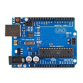
| Microcontroller | Arduino Nano, Uno, or ATmega328P board | Process sensor logic and calculate PWM output signals |
| Sensor Array | 5-channel or 8-channel IR Sensor Bar (e.g., TCRT5000 array) | Detect surface reflectivity across a wide line area |
| Motor Driver | TB6612FNG (MOSFET-based) or L298N (Bipolar) | Control motor direction and speed via PWM |
| Motors | 2x 6V Micro Metal Gearmotors (200–500 RPM) | Provide differential steering and movement |
| Power Supply | 2S LiPo (7.4V) or 2x 18650 Li-ion cells | Provide stable voltage for logic and motor load |
| Chassis | 2-Wheel Differential Drive with Front Caster Wheel | Support balance and high-maneuverability turning |
Infrared Sensing Principles
Line detection relies on differential light absorption. Dark surfaces absorb most light in the infrared spectrum, whereas light surfaces reflect it.
Each sensor node on an IR reflective array contains an IR emitting LED and a phototransistor receiver:
- IR Emission: The emitting diode radiates infrared light toward the ground surface.
- Reflectance: If the ground is white, light reflects back into the phototransistor, lowering its internal resistance and outputting a high analog signal (or low, depending on board active-logic design).
- Absorbance: When the sensor passes over a black electrical tape track, the IR light is absorbed, raising phototransistor resistance.
Using a multi-channel sensor bar (such as a 5-sensor array) allows the robot to sense not just whether it is on or off the line, but how far the center of the robot has drifted from the line path.
Wiring Schematic and Pin Connections
Below is the pin mapping for an Arduino paired with a 5-sensor IR array and a TB6612FNG motor driver module.
Pin Interfacing Table
| Component | Pin Label | Microcontroller Pin | Function |
|---|---|---|---|
| IR Array | OUT1 (Leftmost) | A0 | Left Outer Sensor Input |
| IR Array | OUT2 | A1 | Left Inner Sensor Input |
| IR Array | OUT3 (Center) | A2 | Center Sensor Input |
| IR Array | OUT4 | A3 | Right Inner Sensor Input |
| IR Array | OUT5 (Rightmost) | A4 | Right Outer Sensor Input |
| TB6612FNG | PWMA | D5 (PWM) | Left Motor Speed Control |
| TB6612FNG | AIN1 / AIN2 | D3 / D4 | Left Motor Direction Control |
| TB6612FNG | PWMB | D6 (PWM) | Right Motor Speed Control |
| TB6612FNG | BIN1 / BIN2 | D7 / D8 | Right Motor Direction Control |
| TB6612FNG | STBY | D9 | Motor Driver Standby / Enable |
Note: Connect all module GND lines to a common ground rail. Power the motors directly from the 7.4V battery pack, while supplying 5V logic regulated from the microcontroller to the sensors and driver VM/VCC lines.
Control Theory: Bang-Bang vs. PID Control
Bang-Bang Control Limitations
Simple line followers use binary logic: if the left sensor hits the line, stop the left motor and spin the right motor forward. While easy to write, bang-bang control creates severe vehicle oscillations (jittering), loses traction at high speeds, and frequently misses sharp angles.
Proportional-Integral-Derivative (PID) Control
A PID controller calculates an error value representing how far the line is from the robot's physical center pin. It continuously adjusts motor PWM speeds proportionately to keep the line directly centered under the sensor array.
Error = (Target Line Position) - (Current Calculated Position)
- Proportional (P): Reacts instantly to the current error amount. Higher proportional gain ($K_p$) sharpens turn response but can cause overshooting if set too high.
- Integral (I): Accumulates past errors over time. $K_i$ corrects minor persistent drift or structural mechanical imbalance.
- Derivative (D): Predicts future error trends based on its rate of change. $K_d$ acts as a dampener to prevent vehicle overshoot and smooth out rapid adjustments.
Position Calculation via Weighted Averages
To determine exact line displacement across 5 analog sensors, calculate a weighted position average:
$$\text{Position} = \frac{(0 \times S_0) + (1000 \times S_1) + (2000 \times S_2) + (3000 \times S_3) + (4000 \times S_4)}{S_0 + S_1 + S_2 + S_3 + S_4}$$
If the line is centered over Sensor 2 ($S_2$), the calculated position equals 2000. An optimal baseline error calculation sets Center = 2000, yielding Error = Calculated Position - 2000.
Complete Embedded C++ Code
Below is a production-ready Arduino sketch incorporating weighted position calculations and a tuned PID loop for motor speed modulation.
// Sensor Pin Assignments
const int sensorPins[5] = {A0, A1, A2, A3, A4};
int sensorValues[5];

// Motor Control Pins (TB6612FNG Interface)
const int pinPWMA = 5;
const int pinAIN1 = 3;
const int pinAIN2 = 4;

const int pinPWMB = 6;
const int pinBIN1 = 7;
const int pinBIN2 = 8;
const int pinSTBY = 9;

// Base Motor Speeds
const int BASE_SPEED = 150; // Range: 0 - 255
const int MAX_SPEED  = 220;

// PID Tuning Parameters
float Kp = 0.08;
float Ki = 0.0001;
float Kd = 0.85;

// Global PID Variables
int lastError = 0;
float integral = 0;

void setup() {
  for (int i = 0; i < 5; i++) {
    pinMode(sensorPins[i], INPUT);
  }

  pinMode(pinPWMA, OUTPUT);
  pinMode(pinAIN1, OUTPUT);
  pinMode(pinAIN2, OUTPUT);
  pinMode(pinPWMB, OUTPUT);
  pinMode(pinBIN1, OUTPUT);
  pinMode(pinBIN2, OUTPUT);
  pinMode(pinSTBY, OUTPUT);

  digitalWrite(pinSTBY, HIGH); // Enable motor driver
}

void loop() {
  int position = readLinePosition();
  int error = position - 2000;

  // Compute PID terms
  float P = error;
  integral += error;
  float D = error - lastError;

  // Calculate motor correction signal
  float motorCorrection = (Kp * P) + (Ki * integral) + (Kd * D);
  lastError = error;

  // Calculate distinct motor speeds
  int leftSpeed  = BASE_SPEED + motorCorrection;
  int rightSpeed = BASE_SPEED - motorCorrection;

  // Constrain speeds to PWM bounds [0, 255]
  leftSpeed  = constrain(leftSpeed, 0, MAX_SPEED);
  rightSpeed = constrain(rightSpeed, 0, MAX_SPEED);

  setMotorSpeeds(leftSpeed, rightSpeed);
}

// Function to calculate weighted sensor average
int readLinePosition() {
  long numerator = 0;
  long denominator = 0;

  for (int i = 0; i < 5; i++) {
    // Standard ADC read (0 - 1023)
    int rawVal = analogRead(sensorPins[i]);

    // Invert reading if line is black on white ground
    int reading = 1023 - rawVal;

    // Apply low-value thresholding to ignore surface noise
    if (reading < 150) reading = 0;

    numerator += (long)reading * (i * 1000);
    denominator += reading;
  }

  // Prevent division by zero if all sensors lose the line
  if (denominator == 0) {
    return (lastError < 0) ? 0 : 4000;
  }

  return numerator / denominator;
}

// Motor driving execution interface
void setMotorSpeeds(int speedL, int speedR) {
  // Left Motor Direction Setup
  digitalWrite(pinAIN1, HIGH);
  digitalWrite(pinAIN2, LOW);
  analogWrite(pinPWMA, speedL);

  // Right Motor Direction Setup
  digitalWrite(pinBIN1, HIGH);
  digitalWrite(pinBIN2, LOW);
  analogWrite(pinPWMB, speedR);
}
Practical PID Calibration and Tuning Procedure
Tuning PID constants manually requires a systematic approach. Follow this order to balance response time and system stability:
          +--------------------------------------------+
          |  Set Kp = 0, Ki = 0, Kd = 0                |
          +--------------------------------------------+
                                |
                                v
          +--------------------------------------------+
          |  Increase Kp until robot follows line,     |
          |  but exhibits noticeable oscillation (jitter)|
          +--------------------------------------------+
                                |
                                v
          +--------------------------------------------+
          |  Increase Kd to damp oscillations          |
          |  and smooth out cornering maneuvers        |
          +--------------------------------------------+
                                |
                                v
          +--------------------------------------------+
          |  Add small Ki only if robot consistently   |
          |  drifts off-center on broad curves         |
          +--------------------------------------------+
- Zero Constants: Begin by setting $K_p = 0$, $K_i = 0$, and $K_d = 0$.
- Tune Proportional Gain ($K_p$): Gradually increase $K_p$ until the robot stays on a gently curving track. At this stage, the robot will wobble back and forth along straight paths.
- Tune Derivative Gain ($K_d$): Increase $K_d$ to smooth out the oscillations caused by $K_p$. Higher derivative gains damp rapid changes, allowing the robot to navigate tight corners without losing the line.
- Tune Integral Gain ($K_i$): Keep $K_i$ at zero or a small fractional value (e.g.,
0.0001). Large integral gains accumulate fast during cornering, causing windup that makes the robot overshoot after exiting turns.
Edge Case Handling and Optimization
High-speed tracks present structural challenge points that basic line followers fail to navigate:
1. Handling 90-Degree Angles
When taking sharp 90-degree corners, the track line can slip completely out of the sensor array before the PID controller can react.
- Solution: Detect extreme states. If
OUT1(far left) registers dark while the outer sensors read white, break out of the PID loop temporarily to force a differential pivot turn: drive the left motor backward and the right motor forward until the center sensor detects the line again.
2. Line Gap Crossing
If the track includes gaps in the line, all sensors will suddenly read white, resulting in a denominator of zero in the position algorithm.
- Solution: Modify
readLinePosition()to retain memory of the last known position. If a gap occurs while the robot was centered (lastError ≈ 0), drive straight at baseline speed. If it was turning, maintain the turn until sensor lock is re-established.
Common Mistakes and Hardware Pitfalls
- Voltage Drop Under Motor Load: DC motor startup draws high current, causing voltage dips that can reset the microcontroller. Add a $100\mu\text{F}$ to $470\mu\text{F}$ electrolytic capacitor across the power rail, and isolate logic power using a dedicated voltage regulator.
- Ambient Light Interference: Direct sunlight or overhead fluorescent lighting can saturate phototransistors. Shield your sensor array using a 3D-printed cowl, or set software calibration routines at power-up to adjust analog thresholds dynamic to room lighting.
- Incorrect Caster Height: If your front caster wheel lifts the IR array too high off the surface (>8mm), light reflections decay rapidly, reducing sensor contrast. Maintain sensor-to-ground clearance between 3mm and 5mm for optimal reading accuracy.
Frequently Asked Questions
Why does my line follower wobble rapidly along straight tracks?
Oscillation occurs when proportional gain ($K_p$) is set too high or derivative gain ($K_d$) is too low. Lower your $K_p$ term by 20% to 30%, or increase $K_d$ to damp high-frequency corrections.
Should I use analog or digital outputs from the IR sensor modules?
For intermediate and high-speed implementations, use analog outputs. Digital threshold outputs convert readings to binary values (0 or 1), discarding smooth gradient data. Analog values enable precise weighted position tracking essential for effective PID control.
How do I handle white lines on black backgrounds?
To trace white lines on dark floors, invert your raw sensor readings inside code logic: replace reading = 1023 - rawVal; with reading = rawVal;.
Summary and Next Steps
Building a reliable line-following robot requires balancing hardware assembly, sensor calibration, and software control theory. By upgrading from simple two-state thresholding to weighted analog sensing and PID motor control, your robot can track paths accurately even at higher speeds.
Recommended Next Enhancements:
- Implement automatic sensor auto-calibration routines during startup by spinning the robot left and right over the line for 3 seconds.
- Upgrade to an 8-channel array to broaden the active detection zone on fast sharp turns.
- Incorporate rotary wheel encoders to track distance and execute speed profiling ahead of sharp corners.