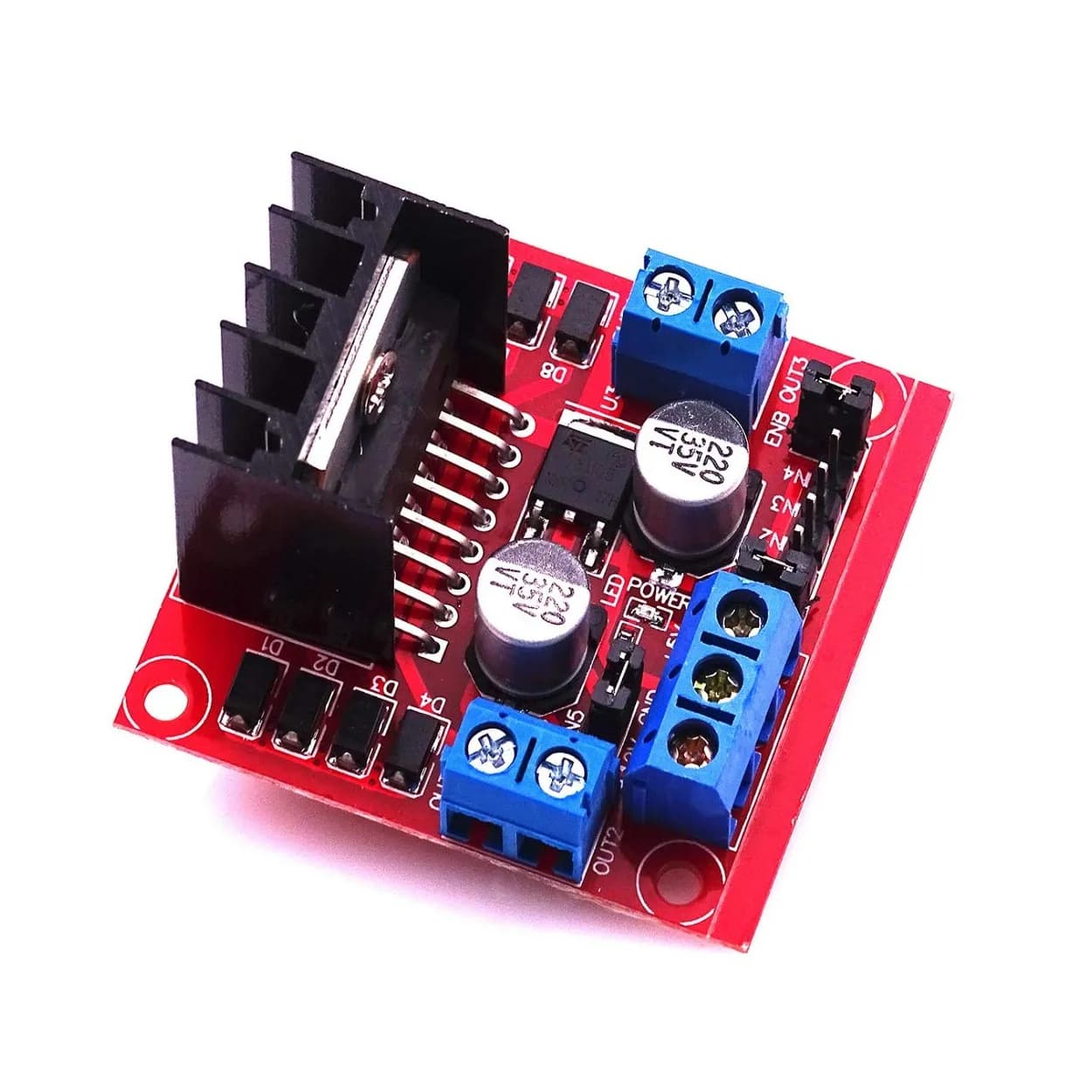
Mastering DC Motor Control with the L298N Driver: Architecture, Wiring, and Code
Learn how to effectively control DC motors using the L298N dual H-bridge module. This guide covers internal architecture, pinouts, PWM speed control, safety considerations, and Arduino integration.

DC motors are fundamental components in robotics and mechatronics projects, providing rotational motion for wheels, winches, and robotic arms. However, microcontrollers like Arduino, ESP32, or STM32 cannot drive DC motors directly. Microcontroller GPIO pins operate at standard logic levels (typically 3.3V or 5V) and can supply only 20–40 mA of current. Inductive loads like DC motors require significantly higher voltages and current drawn in hundreds of milliamperes or several amperes.
The L298N dual H-bridge motor driver module acts as an intermediate power amplifier and logic bridge. It allows low-power microcontroller signals to control high-power DC motors' direction and rotational speed.
This guide covers the internal hardware architecture, electrical characteristics, wiring configurations, direction truth tables, and practical C++ code implementations for driving DC motors with the L298N.
L298N Module Architecture and H-Bridge Basics
To control a DC motor effectively, a motor driver must perform two core functions: bi-directional current flow management (for directional control) and power regulation (for speed control).
The H-Bridge Principle
An H-Bridge is an electronic circuit composed of four switches (transistors or MOSFETs) arranged in an "H" configuration around a central load (the motor).
- Forward Rotation: Closing switches S1 and S4 while leaving S2 and S3 open forces current to flow from the positive supply rail through the motor from left to right.
- Reverse Rotation: Closing switches S2 and S3 while leaving S1 and S4 open reverses the current flow through the motor from right to left.
- Braking (Active Brake): Closing S1 and S2 (or S3 and S4) shorts both motor terminals to the same voltage rail. The motor acts as a generator, dissipating its kinetic energy back into its own windings, causing a rapid stop.
- Coasting (Free Stop): Opening all four switches isolates the motor terminals completely. The motor gradually coast to a halt due to friction.
Warning: Closing S1 and S2 simultaneously (or S3 and S4) creates a direct short circuit between power and ground. This state, known as shoot-through, can instantly destroy the driver transistors. Dedicated driver ICs like the L298 IC feature internal logic logic blocks to prevent shoot-through.
Inside the L298 IC
The core of the L298N module is the L298 multi-watt IC manufactured by STMicroelectronics. It contains two high-voltage, high-current full-bridge drivers designed to accept standard TTL logic levels.
Key hardware specifications of the L298 IC include:
- Driver Type: Dual Full-Bridge Driver
- Operating Supply Voltage ($V_{CC}$): Up to 46V
- Total DC Current: Up to 2A per channel (continuous), 3A peak per channel
- Logic Voltage Range ($V_{SS}$): 4.5V to 7V
- Internal Switch Technology: Bipolar Junction Transistor (BJT) Darlington pairs
The Module Circuitry: Regulators, Jumpers, and Diodes
Most hobbyists and engineers use the red breakout board module rather than the bare IC. The breakout board includes essential passive components and thermal features:
- Onboard 78M05 Voltage Regulator: Converts incoming motor supply voltage into a steady 5V output to power the L298 internal logic circuitry and optionally power the host microcontroller.
- 5V Enable Jumper: Controls whether the onboard 78M05 regulator is active.
- Protection Flyback Diodes: Inductive loads generate high negative voltage spikes (back-EMF) when switched off. The diodes clamp these high-voltage spikes, shielding the internal transistors from inductive kickback.
- Current Sense Pins (SENSE_A, SENSE_B): Exposed on the PCB bottom or tied directly to ground, allowing current-sensing resistors to monitor motor load torque.
L298N Module Pinout and Wiring Interface
Understanding the function of each terminal block and header pin is essential before connecting high-power sources.
                   +-----------------------------------+
                   |           L298N MODULE            |
                   |                                   |
   [Out 1] --------| [OUT1]                     [OUT3] |-------- [Out 3]
   (Motor A)       |                            [OUT4] |-------- (Motor B)
   [Out 2] --------| [OUT2]                            |
                   |                                   |
                   | [12V]  [GND]   [5V]               |
                   +--|-------|------|-----------------+
                      |       |      |
                   Motor V+  GND   5V Out/In
Power Terminal Connections
- 12V Terminal ($V_{CC}$): Main power input for the motors. Despite the label "12V", it operates across a recommended range of 7V to 24V DC.
- GND Terminal: Common ground connection. Must be connected to both the motor power supply negative terminal and the microcontroller ground.
- 5V Terminal: Serves a dual function based on the onboard jumper position:
- Jumper Installed: Acts as a 5V Output (powered by the onboard regulator) to supply external circuits or microcontrollers (limit output current to ~500mA).
- Jumper Removed: Acts as a 5V Input logic supply (must be connected to an external 5V source to power the L298 internal logic).
Logic and Control Pins
- ENA (Enable A): PWM input pin for Channel A (Motor A). Removing the jumper header exposes this pin. Applying a PWM signal varies the speed of Motor A.
- IN1 & IN2: Digital direction control inputs for Motor A.
- IN3 & IN4: Digital direction control inputs for Motor B.
- ENB (Enable B): PWM input pin for Channel B (Motor B).
Directional Logic and Control Truth Table
The direction of rotation and stop behavior of each channel depend on the logic states of the input pins and the enable pin.
| Enable (ENA/ENB) | Input 1 (IN1/IN3) | Input 2 (IN2/IN4) | Motor Mode / Direction |
|---|---|---|---|
| LOW | X (Don't Care) | X (Don't Care) | Motor Disabled (Coast) |
| HIGH | LOW | LOW | Motor Fast Stop (Brake) |
| HIGH | HIGH | LOW | Clockwise (Forward) |
| HIGH | LOW | HIGH | Counter-Clockwise (Reverse) |
| HIGH | HIGH | HIGH | Motor Fast Stop (Brake) |
Power Considerations and 5V Jumper Logic
Using incorrect power supply connections is a common reason for damaged microcontrollers or unstable motor operational states.
Operating with Motor Voltages Between 7V and 12V
When your main power supply is in the 7V to 12V DC range:
- Keep the 5V Enable Jumper installed.
- The onboard 78M05 linear regulator turns the motor power into a stable 5V supply for the L298 logic gates.
- You can tap 5V from the 5V terminal block to power an Arduino board if needed.
Operating with Motor Voltages Above 12V
When motor voltages exceed 12V (up to 24V–35V maximum):
- Remove the 5V Enable Jumper.
- Leaving the jumper on at voltages above 12V causes the linear regulator to overheat and fail due to excessive power dissipation ($P = (V_{in} - 5\text{V}) \times I$).
- Supply an external 5V signal from your microcontroller or an external buck converter directly into the 5V terminal block.
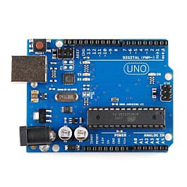
Step-by-Step Wiring with an Arduino
Here is how to connect a single microcontroller (e.g., Arduino Uno) to drive two DC motors independently:
Hardware Connections Table
| Component Pin | Connection Target | Notes |
|---|---|---|
| L298N 12V | Battery Positive (+) | 7V–12V DC Source |
| L298N GND | Battery Negative (-) & Arduino GND | Common Ground Reference |
| L298N 5V | Arduino 5V (if jumper removed) | Power for logic logic |
| L298N ENA | Arduino Pin 9 | PWM Pin for Speed Control A |
| L298N IN1 | Arduino Pin 8 | Direction Control A |
| L298N IN2 | Arduino Pin 7 | Direction Control A |
| L298N IN3 | Arduino Pin 6 | Direction Control B |
| L298N IN4 | Arduino Pin 5 | Direction Control B |
| L298N ENB | Arduino Pin 3 | PWM Pin for Speed Control B |
| OUT1 & OUT2 | Motor A Terminals | Inductive load channel A |
| OUT3 & OUT4 | Motor B Terminals | Inductive load channel B |
Practical C++ Implementation (Arduino Code)
The following example code establishes direct control over directional vectors and speed regulation using Pulse Width Modulation (PWM).
// Pin Definitions for L298N Driver
const int ENA_PIN = 9;  // PWM output to ENA
const int IN1_PIN = 8;  // Logic input IN1
const int IN2_PIN = 7;  // Logic input IN2

const int IN3_PIN = 6;  // Logic input IN3
const int IN4_PIN = 5;  // Logic input IN4
const int ENB_PIN = 3;  // PWM output to ENB

void setup() {
  // Set control pins as outputs
  pinMode(ENA_PIN, OUTPUT);
  pinMode(ENB_PIN, OUTPUT);
  pinMode(IN1_PIN, OUTPUT);
  pinMode(IN2_PIN, OUTPUT);
  pinMode(IN3_PIN, OUTPUT);
  pinMode(IN4_PIN, OUTPUT);

  // Initialize motors to stopped state
  stopMotors();
}

void loop() {
  // Drive both motors forward at 75% speed (PWM value ~190 out of 255)
  driveForward(190);
  delay(2000);

  // Perform active brake
  brakeMotors();
  delay(1000);

  // Drive reverse at full speed (255)
  driveReverse(255);
  delay(2000);

  // Pivot Turn (Motor A Forward, Motor B Reverse)
  pivotTurnLeft(180);
  delay(1500);

  // Stop and wait
  stopMotors();
  delay(3000);
}

// Function to set Motor A state
void setMotorA(int speed, bool forward) {
  // Speed parameter bound between 0 and 255
  speed = constrain(speed, 0, 255);
  analogWrite(ENA_PIN, speed);

  if (forward) {
    digitalWrite(IN1_PIN, HIGH);
    digitalWrite(IN2_PIN, LOW);
  } else {
    digitalWrite(IN1_PIN, LOW);
    digitalWrite(IN2_PIN, HIGH);
  }
}

// Function to set Motor B state
void setMotorB(int speed, bool forward) {
  speed = constrain(speed, 0, 255);
  analogWrite(ENB_PIN, speed);

  if (forward) {
    digitalWrite(IN3_PIN, HIGH);
    digitalWrite(IN4_PIN, LOW);
  } else {
    digitalWrite(IN3_PIN, LOW);
    digitalWrite(IN4_PIN, HIGH);
  }
}

void driveForward(int speed) {
  setMotorA(speed, true);
  setMotorB(speed, true);
}

void driveReverse(int speed) {
  setMotorA(speed, false);
  setMotorB(speed, false);
}

void pivotTurnLeft(int speed) {
  setMotorA(speed, false);
  setMotorB(speed, true);
}

void brakeMotors() {
  digitalWrite(IN1_PIN, HIGH);
  digitalWrite(IN2_PIN, HIGH);
  digitalWrite(IN3_PIN, HIGH);
  digitalWrite(IN4_PIN, HIGH);
  analogWrite(ENA_PIN, 255);
  analogWrite(ENB_PIN, 255);
}

void stopMotors() {
  // Coast to stop
  analogWrite(ENA_PIN, 0);
  analogWrite(ENB_PIN, 0);
  digitalWrite(IN1_PIN, LOW);
  digitalWrite(IN2_PIN, LOW);
  digitalWrite(IN3_PIN, LOW);
  digitalWrite(IN4_PIN, LOW);
}
Technical Limitations and Efficiency Considerations
While the L298N module is affordable and accessible, intermediate developers must account for several inherent hardware trade-offs.
1. Significant Voltage Drop Across Transistors
The internal switches of the L298 are internal BJT output transistors (Darlington pairs). BJT transistors exhibit a notable collector-emitter saturation voltage drop ($V_{CE(sat)}$).
- Typical Voltage Losses: The total internal voltage drop can range between 1.8V to 4.9V depending on current draw.
- Practical Implication: If you supply 12V to the L298N terminal, your motors will only receive approximately 8.5V to 10V. Account for this loss when selecting battery voltages.
2. High Thermal Dissipation
Due to the internal voltage drop, wasted energy converts directly into thermal dissipation ($P = V_{drop} \times I_{load}$).
- When driving motors near 1A to 2A, the aluminum heatsink on the L298N gets hot quickly.
- Forced cooling (such as a 5V fan) or larger custom heat sinks are required for continuous high-current operations.
3. Lack of Low Power / Sleep Mode
Unlike modern driver boards, the L298 IC lacks built-in low-power standby functions. It draws quiescent current continuously even when motors are idle, making it less ideal for compact, battery-critical IoT applications.
Troubleshooting Common L298N Issues
-
Motors do not run, but the L298N board LED turns on: Check whether common ground is connected. The Arduino GND must be connected to the L298N GND pin. Without a shared voltage reference, digital signal levels cannot be interpreted correctly.
-
Motor vibrates or hums without rotating: The supply voltage may be dropping too low due to the internal transistor drop. Alternatively, the PWM duty cycle applied to the enable pins may be below the motor's mechanical stall threshold. Increase the minimum PWM duty cycle value in code (e.g., from 0 to at least 70).
-
Arduino resets whenever motors start: DC motors cause current spikes upon starting, pulling supply rails down and causing a brownout reset on the microcontroller. Use separate power supplies for motors and logic, or add decoupling bulk electrolytic capacitors (e.g., 470µF–1000µF) across the battery supply terminals.
Modern Alternatives to the L298N
When system requirements demand high efficiency, thermal optimization, or compact form factors, consider modern driver IC alternatives:
| Specification / Feature | L298N | TB6612FNG | DRV8833 |
|---|---|---|---|
| Internal Output Topology | BJT Darlington | MOSFET | MOSFET |
| Voltage Drop ($V_{drop}$) | High (~2V to 4V) | Extremely Low ($R_{DS(on)} \approx 0.5\Omega$) | Extremely Low |
| Continuous Current / Channel | 2.0A | 1.2A (3.2A peak) | 1.5A |
| Thermal Efficiency | Poor (Requires Heatsink) | High (Runs Cool) | High |
| Logic Voltage Compatibility | 5V TTL | 2.7V - 5.5V | 2.7V - 10.8V |
Frequently Asked Questions
Can the L298N module drive stepper motors?
Yes. The L298N module contains two full H-bridges, which can control one 4-wire bipolar stepper motor. Inputs IN1 to IN4 drive the two phase coils sequentially.
Can I run a 5V motor using an 8V supply on the L298N?
Yes, but you must scale down the output via PWM. A max PWM value of ~160 (out of 255) effectively limits the average duty cycle voltage delivered across the load.
Why does my L298N logic board stop working when I remove the 5V jumper?
Removing the jumper disconnects the onboard 5V linear regulator. Once removed, you must supply an external 5V signal to the 5V terminal block to power the internal logic IC.
Next Steps
Now that you have mastered basic motor control with the L298N:
- Integrate wheel encoder sensors with digital interrupt pins on your microcontroller to monitor real-time RPM.
- Implement a PID (Proportional-Integral-Derivative) control loop to maintain precise motor speed and rotation under varying load conditions.
- Add an ultrasonic or LiDAR sensor to build an autonomous obstacle-avoiding mobile robot platform.