Ultrasonic Sensors for Robotic Obstacle Avoidance: Principles, Code, and Filtering
Learn how to build robust robotic obstacle avoidance systems using ultrasonic sensors, featuring non-blocking code patterns, noise filtering algorithms, and multi-sensor array design.

Obstacle avoidance is one of the foundational requirements for autonomous mobile robots (AMRs). Whether you are developing a basic differential-drive rover or a complex indoor inspection robot, preventing physical collisions is essential for operational safety and continuous navigation.
Among the various sensing modalities available to robotics developers—such as LiDAR, infrared (IR) rangefinders, stereo vision, and time-of-flight (ToF) optical sensors—ultrasonic rangefinders remain one of the most cost-effective and reliable solutions for short-range detection.
This guide explores the engineering principles, hardware timing, software architecture, and signal processing techniques required to implement high-reliability ultrasonic obstacle avoidance systems.
How Ultrasonic Distance Sensing Works
Ultrasonic sensors operate on the principle of acoustic Time-of-Flight (ToF). The module emits a high-frequency sound wave—typically around 40 kHz, which is beyond the threshold of human hearing—and measures the time elapsed until the sound wave bounces off an object and returns to the receiver.
+------------------+                    +-----------------+
| Microcontroller  |                    | Sensor Module   |
|                  | --- Trigger Pulse ->| (Emitter 40kHz) | ====> Sound Wave
|                  |                    |                 |          |
|                  | <- Echo Duration --| (Receiver)      | <==== Echo Wave
+------------------+                    +-----------------+       [Obstacle]
The Physical Formula
The distance between the sensor and the obstacle is calculated using the speed of sound through air:
$$\text{Distance} = \frac{\text{Time of Flight} \times \text{Speed of Sound}}{2}$$
- Speed of Sound ($v$): In standard air at 20°C, sound travels at approximately 343 meters per second (or 0.0343 centimeters per microsecond).
- Division by 2: The sound wave travels to the obstacle and back, covering twice the total distance to the object.
Substituting the constant speed of sound into the equation yields the practical formula used in robotics firmware:
$$\text{Distance (cm)} = \frac{\text{Time (\mu s)}}{58.3}$$ $$\text{Distance (inches)} = \frac{\text{Time (\mu s)}}{148}$$
Standard Interface Timing
Common modules (such as the HC-SR04, US-100, or HY-SRF05) rely on a simple dual-pin digital interface:
- Trigger Pin (Input): The microcontroller sets this pin
HIGHfor a minimum of 10 microseconds ($\mu s$) to initiate a measurement cycle. - Internal Burst: The sensor's onboard microcontroller emits an 8-cycle sonic burst at 40 kHz.
- Echo Pin (Output): The sensor sets the Echo pin
HIGHsimultaneously with the sonic burst and holds itHIGHuntil the reflected wave is received back. The duration of thisHIGHpulse represents the total round-trip time.
Technical Limitations and Physics-Based Challenges
While ultrasonic sensors are straightforward to operate, relying on them for obstacle avoidance in complex environments introduces physical and environmental challenges that must be addressed in software.
1. Specular Reflection and Incidence Angle
Sound waves behave like light rays on smooth surfaces. If the sensor approaches a flat object (like a wall or cabinet) at an acute angle of incidence (typically greater than 45 degrees relative to the normal line), the sound wave will bounce away from the sensor rather than returning to the receiver.
- Consequence: The sensor reports an open pathway even though a physical barrier is directly in front of the robot at an angle.
2. Acoustic Absorption
Soft materials—such as carpets, curtains, thick clothing, or foam—absorber high-frequency acoustic energy instead of reflecting it.
- Consequence: The echo pulse never returns or returns significantly weakened, causing the sensor to either time out or report an artificially long distance.
3. Acoustic Crosstalk
When multiple ultrasonic sensors fire simultaneously on a single robot, Sensor A may receive the reflected wave generated by Sensor B.
- Consequence: Phantom obstacles or false open paths are registered due to out-of-phase echo reception.
4. Environmental Temperature Sensitivity
The speed of sound in air varies with atmospheric temperature according to the approximation:
$$v \approx 331.3 + (0.606 \times T) \quad \text{m/s}$$
Where $T$ is the ambient temperature in degrees Celsius. A shift from 0°C to 30°C changes the speed of sound from ~331 m/s to ~349 m/s, introducing roughly a 5% measurement error if left uncompensated.
Software Architecture: Moving Beyond Blocking Code
A common mistake in intermediate robotics projects is relying on blocking delay functions like pulseIn() in Arduino environments.
pulseIn() halts the microcontrollers execution thread while waiting for the Echo pin to transition from HIGH to LOW. If no echo returns (e.g., out-of-range targets), the processor can freeze for up to 30 milliseconds per reading. In a robot moving at 1 meter per second, a 30 ms delay translates to 3 centimeters of unmonitored travel per sensor, leading to sluggish motor control and potential collisions.
Non-Blocking State Machine Approach
To maintain deterministic control loops, distance measurement should be integrated into a non-blocking timing loop or handled via hardware timer interrupts.
Below is an architectural approach using a non-blocking asynchronous timing model in C++:
// Non-blocking distance sensing module state machine
enum SensorState {
  IDLE,
  TRIGGERING,
  WAITING_FOR_ECHO,
  READING_COMPLETE
};

struct UltrasonicSensor {
  uint8_t triggerPin;
  uint8_t echoPin;
  SensorState state;
  unsigned long lastActionMicros;
  unsigned long echoStartTime;
  unsigned long pulseDuration;
  float calculatedDistanceCm;
};

void updateSensor(UltrasonicSensor &sensor) {
  unsigned long currentMicros = micros();

  switch (sensor.state) {
    case IDLE:
      digitalWrite(sensor.triggerPin, LOW);
      if (currentMicros - sensor.lastActionMicros >= 2000) { // Ensure clear pin state
        digitalWrite(sensor.triggerPin, HIGH);
        sensor.lastActionMicros = currentMicros;
        sensor.state = TRIGGERING;
      }
      break;

    case TRIGGERING:
      if (currentMicros - sensor.lastActionMicros >= 10) { // 10us trigger pulse
        digitalWrite(sensor.triggerPin, LOW);
        sensor.lastActionMicros = currentMicros;
        sensor.state = WAITING_FOR_ECHO;
      }
      break;

    case WAITING_FOR_ECHO:
      // Note: Interrupt driven echo reading is ideal, but state polling shown here
      if (digitalRead(sensor.echoPin) == HIGH) {
        sensor.echoStartTime = micros();
        // Shift state to monitoring pulse fall
      }
      // Implementation detail: Handle timeout if echo stays high or low too long
      break;

    default:
      break;
  }
}
Filtering Noise for Reliable Obstacle Avoidance
Raw ultrasonic data streams frequently contain spikes caused by physical reflections, cross-talk, or electronic noise. Using unfiltered data directly inside motor control logic causes jittery behavior, unnecessary emergency stops, or missed obstacles.
Comparing Filtering Algorithms
| Filter Type | Advantages | Disadvantages | Best Use Case |
|---|---|---|---|
| Moving Average | Smooths minor variance; very light computation. | Highly sensitive to extreme single-sample outliers (spikes). | Static sensor monitoring slow ambient changes. |
| Median Filter | Completely rejects single-point impulse noise and hardware timeouts. | Introduces minor phase delay depending on window size. | Mobile robot obstacle detection subject to physical spikes. |
| Exponential Moving Average (EMA) | Fast execution; requires minimal RAM (no arrays required). | Outliers still skew output slightly. | Continuous smooth distance tracking for speed matching. |
Implementing a Moving Median Filter
A 3-sample or 5-sample median filter is the industry standard for low-cost ultrasonic processing. It takes $N$ recent samples, sorts them numerically, and selects the middle value, discarding extreme high or low anomalies.
#define WINDOW_SIZE 5

class MedianFilter {
private:
  float buffer[WINDOW_SIZE];
  uint8_t index = 0;

public:
  MedianFilter() {
    for (uint8_t i = 0; i < WINDOW_SIZE; i++) buffer[i] = 0.0;
  }

  float update(float newValue) {
    buffer[index] = newValue;
    index = (index + 1) % WINDOW_SIZE;

    // Create a temporary copy to sort
    float sorted[WINDOW_SIZE];
    for (uint8_t i = 0; i < WINDOW_SIZE; i++) {
      sorted[i] = buffer[i];
    }

    // Insertion sort for small array
    for (uint8_t i = 1; i < WINDOW_SIZE; i++) {
      float key = sorted[i];
      int8_t j = i - 1;
      while (j >= 0 && sorted[j] > key) {
        sorted[j + 1] = sorted[j];
        j--;
      }
      sorted[j + 1] = key;
    }

    // Return middle element
    return sorted[WINDOW_SIZE / 2];
  }
};
System Integration: Obstacle Avoidance Control Strategies
Once stable, filtered distance readings are available, the robot needs a control policy to react to obstacles.
Strategy 1: Multi-Sensor Array Routing
The most common hardware configuration uses three fixed ultrasonic sensors: Center, Left, and Right.
          [ Center Sensor ]
                 /\
     [ Left ]   /  \   [ Right ]
     Sensor    /    \   Sensor
       \      /      \    /
        +----------------+
        |   Robot Base   |
        +----------------+
To prevent acoustic crosstalk between adjacent sensors:
- Sequential Interleaved Firing: Trigger sensors sequentially rather than simultaneously. Fire Center $\rightarrow$ Wait 30ms $\rightarrow$ Fire Left $\rightarrow$ Wait 30ms $\rightarrow$ Fire Right.
Finite State Machine (FSM) Decision Matrix
enum NavigationState {
  STATE_FORWARD,
  STATE_EVALUATE_TURN,
  STATE_TURN_LEFT,
  STATE_TURN_RIGHT,
  STATE_REVERSE
};

const float CRITICAL_DISTANCE_CM = 20.0;
const float WARNING_DISTANCE_CM = 45.0;

NavigationState determineNavigationState(float leftCm, float centerCm, float rightCm) {
  if (centerCm < CRITICAL_DISTANCE_CM || leftCm < (CRITICAL_DISTANCE_CM / 2) || rightCm < (CRITICAL_DISTANCE_CM / 2)) {
    // Immediate danger of collision
    if (leftCm > rightCm) {
      return STATE_TURN_LEFT;
    } else {
      return STATE_TURN_RIGHT;
    }
  }
  else if (centerCm < WARNING_DISTANCE_CM) {
    // Obstacle ahead, pick path of least resistance
    return (leftCm > rightCm) ? STATE_TURN_LEFT : STATE_TURN_RIGHT;
  }

  return STATE_FORWARD;
}
Strategy 2: Single Sensor with Servo Scanning
For lower-budget platforms with limited digital I/O pins, a single ultrasonic sensor mounted on a 180-degree micro servo motor can scan the environment.
- Robot moves FORWARD while servo points straight (90°).
- When the center threshold is breached, the robot halts drive motors.
- The servo sweeps to 30° (Right) and reads distance, then sweeps to 150° (Left) and reads distance.
- The control software selects the direction with the maximum open clearance.
- Motors execute a zero-radius turn toward the chosen direction, the servo re-centers to 90°, and forward propulsion resumes.
Practical Implementation: Complete Arduino Sketch
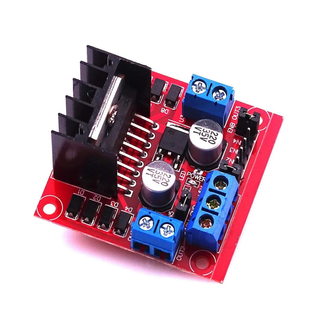
The following sketch demonstrates a robust non-blocking, median-filtered obstacle avoidance system driving a simple two-wheel differential robot via a dual H-bridge motor driver.
#include <Arduino.h>

// Pin Definitions
const uint8_t TRIG_PIN = 9;
const uint8_t ECHO_PIN = 8;

const uint8_t MOTOR_LEFT_FORWARD = 4;
const uint8_t MOTOR_LEFT_BACKWARD = 5;
const uint8_t MOTOR_RIGHT_FORWARD = 6;
const uint8_t MOTOR_RIGHT_BACKWARD = 7;

// Operational Thresholds
const float SAFE_THRESHOLD_CM = 30.0;
const float MIN_VALID_RANGE_CM = 2.0;
const float MAX_VALID_RANGE_CM = 400.0;

// Timing Constants
const unsigned long SENSOR_INTERVAL_MS = 40; // ~25Hz polling rate
unsigned long lastSensorReadTime = 0;

// Simple 3-sample median filter variables
float p1 = 0, p2 = 0, p3 = 0;

float getMedian(float a, float b, float c) {
  if ((a <= b && b <= c) || (c <= b && b <= a)) return b;
  if ((b <= a && a <= c) || (c <= a && a <= b)) return a;
  return c;
}

float readDistanceDirect() {
  digitalWrite(TRIG_PIN, LOW);
  delayMicroseconds(2);
  digitalWrite(TRIG_PIN, HIGH);
  delayMicroseconds(10);
  digitalWrite(TRIG_PIN, LOW);

  // Read pulse width with a 25ms timeout (~400cm max range)
  long duration = pulseIn(ECHO_PIN, HIGH, 25000);

  if (duration == 0) {
    return MAX_VALID_RANGE_CM; // Timeout, assume path clear
  }

  float distance = (float)duration * 0.0343 / 2.0;

  if (distance < MIN_VALID_RANGE_CM || distance > MAX_VALID_RANGE_CM) {
    return MAX_VALID_RANGE_CM;
  }

  return distance;
}

void setMotors(bool leftFwd, bool leftBwd, bool rightFwd, bool rightBwd) {
  digitalWrite(MOTOR_LEFT_FORWARD, leftFwd);
  digitalWrite(MOTOR_LEFT_BACKWARD, leftBwd);
  digitalWrite(MOTOR_RIGHT_FORWARD, rightFwd);
  digitalWrite(MOTOR_RIGHT_BACKWARD, rightBwd);
}

void setup() {
  pinMode(TRIG_PIN, OUTPUT);
  pinMode(ECHO_PIN, INPUT);

  pinMode(MOTOR_LEFT_FORWARD, OUTPUT);
  pinMode(MOTOR_LEFT_BACKWARD, OUTPUT);
  pinMode(MOTOR_RIGHT_FORWARD, OUTPUT);
  pinMode(MOTOR_RIGHT_BACKWARD, OUTPUT);

  // Initialize motors off
  setMotors(false, false, false, false);
}

void loop() {
  unsigned long currentTime = millis();

  if (currentTime - lastSensorReadTime >= SENSOR_INTERVAL_MS) {
    lastSensorReadTime = currentTime;

    // Shift filter samples
    p3 = p2;
    p2 = p1;
    p1 = readDistanceDirect();

    float currentDistance = getMedian(p1, p2, p3);

    // Obstacle Avoidance Logic
    if (currentDistance < SAFE_THRESHOLD_CM) {
      // Obstacle detected: Turn in place to clear path
      setMotors(false, true, true, false); // Turn Left
    } else {
      // Clear path: Move Forward
      setMotors(true, false, true, false); // Drive Forward
    }
  }
}
Hardware Considerations and Common Pitfalls
1. Power Supply Decoupling and Voltage Brownouts
DC motors draw high surge currents (stall current) during rapid acceleration or sudden directional shifts. If your ultrasonic sensors share the exact same power rails without isolation, the resulting voltage drops (brownouts) can corrupt sensor logic or reset the microcontroller.
- Mitigation: Power logic components and motors from separate regulated rails, or insert a bulk electrolytic capacitor (e.g., 470 $\mu\text{F}$ to 1000 $\mu\text{F}$) across the motor power supply leads, along with 0.1 $\mu\text{F}$ ceramic decoupling capacitors near the sensor VCC pins.
2. Voltage Level Mismatches
Classic ultrasonic modules (like the standard HC-SR04) operate at 5V logic. If connected directly to modern 3.3V microcontrollers (such as ESP32, STM32, or modern ARM processors), the 5V output on the Echo pin can damage the input GPIO pins.
- Mitigation: Use a simple resistor voltage divider on the Echo pin line (e.g., a 1k$\Omega$ resistor inline and a 2k$\Omega$ resistor connected to GND) or an inline bidirectional logic level shifter.
Sensor Echo (5V) ---> [ 1k Ohm ] ---> Microcontroller GPIO (3.3V)
                               |
                           [ 2k Ohm ]
                               |
                              GND
3. Sensor Blind Spots (Dead Zones)
Standard ultrasonic modules have a minimum range limitation (typically 2 cm to 3 cm). Objects located closer than this distance fail to provide enough delay between trigger termination and echo reception, causing false readings or infinite timeouts.
- Mitigation: Mount sensors recessed slightly inside the robot frame so that physical contact points occur outside the sensor's dead zone threshold.
Summary and Next Steps
Ultrasonic sensors provide a reliable, low-cost solution for real-time obstacle detection in mobile robotics. Achieving high system performance requires moving beyond simple blocking example code:
- Respect the physics of acoustic signals, accounting for specular reflection and absorption.
- Apply median filtering to eliminate spurious noise spikes and timeout artifacts.
- Construct non-blocking software architecture to ensure motor control loops remain responsive.
- Prevent acoustic crosstalk by sequencing trigger pulses in multi-sensor configurations.
To extend your robot's capabilities, consider blending ultrasonic distance readings with complementary sensors—such as optical infrared sensors or bumper switches—using a multi-sensor sensor fusion approach. This combined architecture covers the physical blind spots of individual sensor technologies, creating a truly robust navigation system.