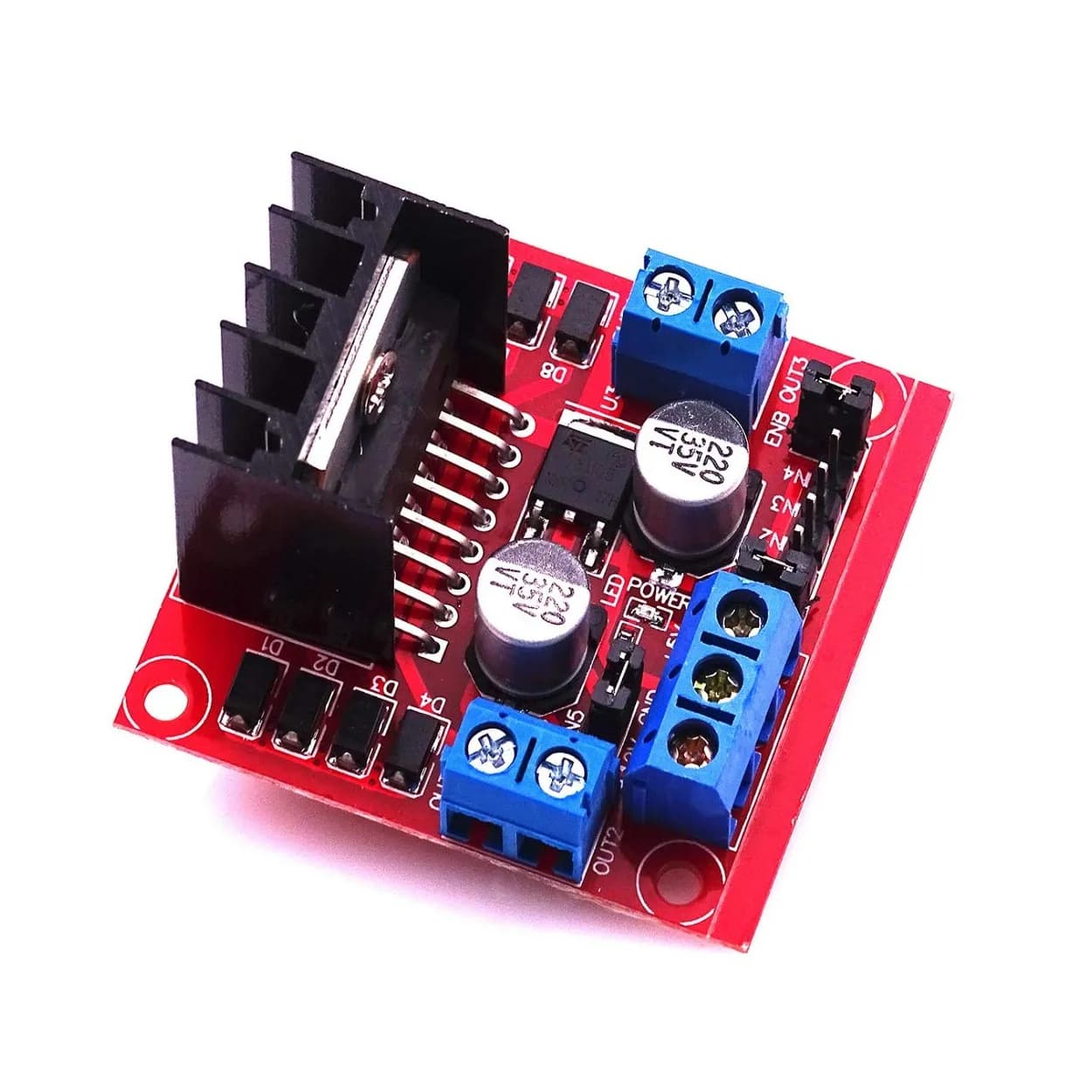
Understanding Stepper Motors: Operating Principles, Drive Modes, and Control Strategies
Learn how stepper motors work from the inside out. This guide covers hybrid rotor architecture, unipolar vs. bipolar configurations, microstepping physics, dynamic torque curves, and practical driver circuits.

Stepper motors are fundamental actuators in precision motion control systems. Unlike standard DC motors that spin continuously when powered or servo motors that rely on closed-loop positional feedback, stepper motors move in discrete angular increments. This discrete motion allows engineers to achieve precise positioning and speed control open-loop—without needing expensive optical encoders or resolvers.
Whether you are designing a 3D printer, a CNC milling machine, a robotic arm, or an automated camera slider, understanding the mechanical construction, driving topologies, and control physics of stepper motors is essential for optimizing performance and avoiding thermal or mechanical failures.
1. Stepper Motor Architecture & Core Mechanics
At its core, a stepper motor is a brushless DC synchronous motor that divides a full mechanical rotation into a fixed number of steps. The angular rotation per step is called the step angle ($\theta_s$). Common step angles are 1.8° (200 steps per revolution) and 0.9° (400 steps per revolution).
Internally, stepper motors consist of a stationary stator carrying copper windings and a rotating rotor attached to the drive shaft. Depending on the rotor design, stepper motors fall into three main categories:
Permanent Magnet (PM) Stepper
The rotor is constructed with alternating North and South magnetic poles parallel to the rotor shaft. They feature low tooth counts, resulting in larger step angles (typically 7.5° to 15°). PM motors yield moderate torque at relatively low manufacturing costs.
Variable Reluctance (VR) Stepper
The rotor is made of a soft magnetic iron core with teeth, lacking permanent magnets. When a stator phase is energized, magnetic flux creates a reluctance torque that pulls the nearest rotor teeth into alignment to minimize magnetic reluctance (the magnetic equivalent of electrical resistance). VR motors have low detent torque (torque when unpowered) and smaller step angles, but lower magnetic density.
Hybrid Synchronous Stepper
The hybrid stepper motor combines the best characteristics of PM and VR designs to maximize torque in a compact frame size.
A hybrid rotor consists of two soft iron tooth caps sandwiched around an axially magnetized permanent magnet core:
- Cap 1 (North Pole): Features 50 radially arrayed teeth.
- Cap 2 (South Pole): Also features 50 teeth, but offset angularly by half a tooth pitch ($3.6^\circ$) relative to Cap 1.
The stator typically contains 8 poles with multi-tooth faces wound with copper coils. When current passes through a pair of stator windings, it creates magnetic poles that attract the teeth of one rotor cap while repelling the offset teeth of the other cap.
$$\text{Step Angle } (\theta_s) = \frac{360^\circ}{N_r \times m}$$
Where $N_r$ is the number of rotor teeth on a single cap (typically 50) and $m$ is the number of effective stator phase states (typically 4 for a two-phase motor).
$$\theta_s = \frac{360^\circ}{50 \times 4} = 1.8^\circ \text{ per step}$$
2. Unipolar vs. Bipolar Winding Topologies
How copper wire is wound around the stator poles dictates the electrical driver topology required to actuate the motor. Stepper motors are broadly categorized into Unipolar and Bipolar configurations.
       UNIPOLAR COIL                        BIPOLAR COIL
   (Center-tapped winding)              (Single continuous coil)

      A1 o--- Phase A ---o A2              A1 o--- Phase A ---o A2
                 |
                 o Common (V+)
Unipolar Steppers
Unipolar windings feature a center tap on each phase coil. The center tap is typically connected to the positive supply voltage ($V_{CC}$), while the outer ends of the coils are alternately switched to ground using single low-side transistors (such as MOSFETs or Darlington arrays).
- Advantage: Driving circuitry is simple and inexpensive. Current always flows in the same direction through a given half-coil, eliminating the need to reverse voltage polarity across the terminals.
- Disadvantage: Only 50% of the copper winding volume is energized at any given instant, reducing the motor's volume-to-torque density by roughly 30% compared to a bipolar motor of the same physical size.
Bipolar Steppers
Bipolar windings contain no center tap; each phase consists of a single continuous coil winding. To switch the magnetic field polarity of a phase pole, the direction of current flowing through the coil must be reversed. This requires an H-Bridge driver circuit (four switching transistors per phase).
- Advantage: 100% of the coil copper is utilized during operation, maximizing torque output and energy efficiency for a given frame size.
- Disadvantage: Requires more complex driver hardware (two full H-bridges for a 2-phase motor).
Wiring Configuration Summary
| Lead Count | Motor Type | Wiring Description | Driving Mode Options |
|---|---|---|---|
| 4 Wires | Bipolar | Two isolated phase coils (A+, A-, B+, B-). | Bipolar Driver only. |
| 5 Wires | Unipolar | Two coils with center taps connected internally to a single common wire. | Unipolar Driver only. |
| 6 Wires | Unipolar / Bipolar | Two coils, each with an independent center tap. | Can run as Unipolar (use center taps) or Bipolar (leave center taps disconnected). |
| 8 Wires | Universal | Four separate individual half-coils. | Can be wired in Series (high inductance/torque at low speed), Parallel (low inductance/high speed), or Unipolar. |
3. Excitation Schemes and Stepping Modes
The sequence and ratio of currents applied to the stator phases determine the resolution, smoothness, and output torque of the motor.
Wave Drive (One-Phase On)
Only one phase is energized at a time (e.g., Phase A $\rightarrow$ Phase B $\rightarrow$ Phase -A $\rightarrow$ Phase -B).
- Torque: Low (only half the magnetic field capacity is utilized).
- Application: Rarely used in modern engineering except where power saving is critical.
Full-Step Drive (Two-Phase On)
Two phases are energized simultaneously with full nominal current (e.g., Phase A+B $\rightarrow$ Phase B+-A $\rightarrow$ Phase -A+-B $\rightarrow$ Phase -B+A).
- Torque: Maximum holding torque (approximately $1.414 \times$ single-phase torque).
- Resolution: Standard resolution (e.g., 200 steps/rev for a 1.8° motor).
- Drawback: High vibration and noticeable noise due to abrupt mechanical torque transitions.
Half-Stepping
Alternates between one-phase-on and two-phase-on states. This doubles the angular resolution (e.g., 400 steps/rev or 0.9° per step).
- Smoothness: Noticeably smoother motion than full-stepping.
- Torque Variation: Torque fluctuates slightly between single-phase states ($100%$ torque) and two-phase states ($141%$ torque) unless current scaling is applied by the driver.
Microstepping
Microstepping splits full mechanical steps into sub-steps by energizing both phases simultaneously with continuously variable, pulse-width-modulated (PWM) sinusoidal currents:
$$I_A = I_{max} \cdot \cos(\phi)$$ $$I_B = I_{max} \cdot \sin(\phi)$$
Where $\phi$ represents the electrical angle corresponding to the target sub-step position within a full step cycle.
Full Step:   [100% A, 0% B]  -->  [0% A, 100% B]
1/4 Microstep Sequence:
  Step 0: I_A = 100%,  I_B = 0%
  Step 1: I_A =  92%,  I_B = 38%
  Step 2: I_A =  71%,  I_B = 71%
  Step 3: I_A =  38%,  I_B = 92%
  Step 4: I_A =   0%,  I_B = 100%
               MICROSTEPPING CURRENT WAVEFORMS
Current (I)
  ^
+I|     ,---.         Phase A       ,---.
  |    /     \                     /     \
 0|---/-------\-------------------/-------\---> Time
  |  /         \                 /         \
-I| '           `---'         `-'           `
  |       ,---.         Phase B       ,---.
  |      /     \                     /     \
  0-----+-------+-------------------+-------+-->
Advantages of Microstepping:
- Resonance Elimination: Dramatically suppresses low-frequency mechanical vibration and noise.
- High Resolution: Allows division of a 1.8° step into 1/16, 1/32, 1/64, or even 1/256 sub-steps.
Critical Microstepping Trade-off:
Microstepping improves positional resolution and acoustic smoothness, but incremental holding torque per microstep decreases significantly. The incremental torque output for a single microstep division $N$ is:
$$T_{incremental} = T_{holding} \times \sin\left(\frac{90^\circ}{N}\right)$$
At 1/64 microstepping, the incremental torque per single microstep drop is roughly $2.45%$ of full holding torque. If friction or load torque exceeds this value, the motor shaft will not move physically until several microstep command pulses accumulate!
4. Electrical Dynamics, Chopper Drivers, and Torque Curves
Understanding the electrical time constants of motor coils is essential to driving stepper motors effectively at higher speeds.
Inductance and the L/R Time Constant
A stepper coil has resistance ($R$) and self-inductance ($L$). When a DC voltage ($V$) is applied across a coil, current does not rise instantly; it increases exponentially according to the time constant $\tau = \frac{L}{R}$:
$$i(t) = \frac{V}{R} \left( 1 - e^{-\frac{t}{\tau}} \right)$$
As the motor spins faster, the time available to ramp current into each phase during a step interval decreases. At high step frequencies, current cannot reach its nominal value before the phase is switched off, causing torque to drop off sharply.
Back EMF
As the permanent magnet rotor spins inside the stator, it acts as a generator, creating a counter-voltage known as Back Electromotive Force (Back EMF):
$$E_{back} = K_e \cdot \omega$$
Where $K_e$ is the motor's voltage constant and $\omega$ is rotational velocity. Back EMF opposes the applied driver voltage, reducing the effective voltage driving current into the windings:
$$I_{coil} \approx \frac{V_{driver} - E_{back}}{R}$$
At higher RPM, $E_{back}$ approaches $V_{driver}$, reducing coil current—and output torque—to zero.
Constant-Current (Chopper) Drivers
To overcome inductive lag and Back EMF, modern stepper drivers (e.g., A4988, DRV8825, TMC2209) use PWM Chopper Current Control:
- High DC supply voltage (e.g., 24V or 48V) is applied to a coil rated for much lower voltage (e.g., 2.8V).
- The higher voltage forces current to ramp up rapidly through the coil's inductance.
- An internal sense resistor monitors coil current. Once current hits a preset threshold ($I_{trip}$), the driver turns off the power switches for a short duration (off-time chopping), controlling current at the set limit via high-frequency PWM.
               CHOPPER DRIVER CURRENT WAVEFORM
Current (I)
  ^
  |      / \ / \ / \ / \ / \  <-- Chopping around I_trip
  |     /   V   V   V   V   V
  |    /
  |   /  <-- Rapid current rise driven by high V_supply
  +--------------------------------------------------> Time
Reading the Speed-Torque Curve
 Torque
   ^
   | [Holding Torque]
   |--------+
   |        | \
   |        |  \  Pull-Out Torque Curve
   |        |   \
   |  Pull-In|    \
   |  Torque |     \
   +--------+-------+-----------------> Speed (Steps/sec)
            ^ Start/Stop limit
- Holding Torque: Maximum static torque the motor can withstand while stationary without slipping position.
- Detent Torque: Unpowered magnetic resistance when the rotor is moved manually.
- Pull-In Torque Curve: Maximum torque under which the motor can start, stop, or reverse instantaneously without losing synchronization.
- Pull-Out Torque Curve: Maximum torque the motor can generate at a given continuous speed once accelerated up to speed. Operating above this curve causes the motor to stall.
5. Driving Interfaces and Code Implementation
Modern dedicated stepper drivers simplify host microcontroller programming by reducing control signals down to two primary digital lines: STEP (Pulse) and DIR (Direction).
- DIR Line: High voltage sets clockwise rotation; Low voltage sets counter-clockwise rotation.
- STEP Line: Each rising edge triggers the driver to advance the internal state table by one microstep.
C++ Hardware Implementation (Non-blocking Step Pulse Generation)
The following example code illustrates pulse-generation logic for an Arduino or similar microcontroller using hardware timing concepts. To prevent step slipping, acceleration profiles gradually increase pulse frequencies:
// Pin definitions for standard Step/Dir Driver (e.g., TMC2209, DRV8825)
const uint8_t PIN_STEP = 3;
const uint8_t PIN_DIR  = 4;

// Operational Parameters
unsigned long stepIntervalMicros = 1000; // Time between steps (Controls Speed)
unsigned long lastStepTime = 0;
bool stepPinState = LOW;

void setup() {
    pinMode(PIN_STEP, OUTPUT);
    pinMode(PIN_DIR, OUTPUT);

    // Set initial rotational direction
    digitalWrite(PIN_DIR, HIGH); // HIGH = CW, LOW = CCW
}

void loop() {
    unsigned long currentMicros = micros();

    // Generate non-blocking step pulses based on interval timing
    if (currentMicros - lastStepTime >= stepIntervalMicros) {
        lastStepTime = currentMicros;

        // Toggle Step Pin to generate pulse edge
        stepPinState = !stepPinState;
        digitalWrite(PIN_STEP, stepPinState);
    }

    // Dynamic speed change logic / linear acceleration profiles can update
    // stepIntervalMicros inside a real-time motion control loop.
}
6. Practical Design Considerations & Troubleshooting
Mechanical Resonance and Mid-Band Instability
Stepper motor systems are prone to mechanical resonance near natural system frequencies (typically between 50 Hz and 200 Hz). When step frequencies match the natural frequency of the motor-load system, oscillations amplify, leading to step loss or stalling.
Mitigation Tactics:
- Utilize microstepping drivers to smooth out excitation steps.
- Implement mechanical dampers (flywheels or elastomeric couplings) on motor shafts.
- Accelerate rapidly through known resonance frequency zones.
Thermal Management
Stepper motors are designed to operate at elevated temperatures; surface temperatures reach 70°C to 80°C under normal rated current. Unlike servos, open-loop steppers draw full rated current even when holding a stationary position.
- Set driver current potentiometers ($V_{ref}$) strictly within the rated RMS current limit of the motor.
- Use active dynamic current scaling (e.g., TMC series drivers reduce current automatically to 50% when stationary).
Causes of Missed Steps
- Excessive Acceleration: Attempting to transition instantly from standstill to high velocity exceeding the rotor inertia capacity.
- Voltage Starvation: Operating a high-speed motion profile using low input supply voltage (e.g., 12V instead of 24V/36V).
- Resonance Stalling: Running continuously at low-speed natural resonance frequencies without microstepping.
- Over-temperature Shutdown: Driver IC overheating and thermal throttling due to insufficient heatsinking or airflow.
7. Stepper Motors vs. Alternative Actuators
| Parameter | Stepper Motor | Brushed DC Motor | Brushless DC (BLDC) Motor | Servo Motor (BLDC + Encoder) |
|---|---|---|---|---|
| Positioning Method | Open-loop counting | None (Requires encoder) | None (Requires encoder) | Closed-loop feedback |
| Low-Speed Torque | High | Low | Low-to-Moderate | Moderate-to-High |
| High-Speed Torque | Drops significantly | High | Very High | Constant up to rated RPM |
| Cost & Complexity | Low-to-Moderate | Very Low | Moderate | High |
| Holding Position | Full torque stationary | Zero static torque | Zero static torque | Full torque (active drive) |
8. Frequently Asked Questions
Why do stepper motors draw full current when stationary?
Unlike DC or servo motors that draw current proportional to applied mechanical load, open-loop stepper motors consume continuous current to generate static magnetic fields capable of resisting external forces (Holding Torque).
How do I calculate Vref for my stepper driver module?
For typical driver breakouts like the A4988 or DRV8825, $V_{ref}$ sets the output current limit based on internal sense resistor values ($R_s$). For an A4988 driver module:
$$I_{max} = \frac{V_{ref}}{8 \times R_s}$$
Check the onboard sense resistor (commonly R100 = 0.10 $\Omega$ or R050 = 0.05 $\Omega$) before calculating $V_{ref}$ to avoid overcurrent damage.
Does microstepping increase positional accuracy?
Microstepping increases positional resolution, but not necessarily absolute positioning accuracy. Friction, load dynamics, and detent forces can distort microstep alignment. For absolute high precision under varying loads, closed-loop stepper systems (steppers fitted with encoders) or gearbox reducers are recommended.
Summary
Stepper motors are ideal solutions for precise, deterministic positioning applications. By selecting the correct motor topology (typically hybrid bipolar for maximum torque density), pairing it with a high-voltage chopper driver, selecting appropriate microstepping levels, and tailoring linear acceleration ramps, engineers can build quiet, robust, and highly reliable motion systems.