Using Servo Motors in Robotics: A Complete Beginner's Guide
Learn how servo motors work, how to connect and control them using microcontrollers like Arduino, and how to avoid common practical mistakes in robotics projects.

Servo motors are among the most essential components in modern robotics. Unlike standard direct current (DC) motors that continuously spin when connected to power, a servo motor can move to a specific angle and hold its position accurately. This ability makes servo motors ideal for controlling mechanical arms, steering mechanisms on rover vehicles, pan-tilt camera mounts, and legged robots.
For beginners entering robotics, learning how to select, wire, and control servo motors is a foundational skill. This guide explains how servo motors operate, how to wire them correctly, how to program them using microcontrollers like Arduino, and how to troubleshoot common beginner mistakes.
What is a Servo Motor and How Does It Work?
A servo motor (often simply called a servo) is an electromechanical device that rotates or moves an output shaft with high angular precision. It operates as a closed-loop feedback system, meaning it constantly monitors its output position and makes real-time corrections to ensure the shaft remains at the target angle.
The Internal Components of a Hobby Servo
Inside a standard hobby servo casing, you will find four main components:
- DC Motor: Provides the rotational movement.
- Gearbox: Reduces the high speed of the internal DC motor while significantly increasing its torque (rotational force).
- Potentiometer (Position Sensor): A variable resistor connected to the output shaft that measures the current physical angle of the shaft.
- Control Circuit Board: Compares the target signal sent from your microcontroller with the current position reported by the potentiometer, adjusting power to the motor accordingly.
       +-------------------------------------------------+
       |                  Servo Casing                   |
       |                                                 |
Input  |  +---------+   +------------+   +------------+  |  Output
Signal |->| Control |-->|  DC Motor  |-->|  Gearbox   |--|-> Shaft
       |  | Circuit |   +------------+   +------------+  |
       |  +---------+                          |         |
       |       ^                               v         |
       |       |       +---------------+       |         |
       |       +-------| Potentiometer |<------+         |
       |               +---------------+                 |
       +-------------------------------------------------+
Pulse Width Modulation (PWM) Control
Servo motors do not rely on varying voltage levels to set their angle. Instead, they receive a command signal using Pulse Width Modulation (PWM).
A standard hobby servo expects a pulse every 20 milliseconds (a frequency of 50 Hz). The duration or width of the high pulse determines the angle of the shaft:
- 1.0 millisecond pulse: Rotates the servo to 0 degrees (far left).
- 1.5 millisecond pulse: Rotates the servo to 90 degrees (center neutral position).
- 2.0 millisecond pulse: Rotates the servo to 180 degrees (far right).
If the signal pulse stays at 1.5 ms, the control board continuously applies power to the internal DC motor to lock the shaft at 90 degrees. If an external force attempts to push the shaft out of alignment, the potentiometer detects the displacement, and the control circuit applies counteracting force to hold position.
Types of Servo Motors Used in Robotics
Before picking a servo motor for your robot, it is crucial to understand the main categories available on the market.
1. Positional Rotation vs. Continuous Rotation
- Positional Rotation Servos (Standard 180°): The output shaft rotates within a limited arc—typically 0° to 180° (or 270° in some models). Internal physical stops prevent full 360° rotation. These are used for mechanical joints, steering levers, and robotic hands.
- Continuous Rotation Servos (360°): The internal potentiometer is replaced with fixed resistors or disconnected from the shaft, and physical stops are removed. Instead of commanding a specific angle, PWM signals command rotational speed and direction. A 1.5 ms pulse stops the motor, while values above or below 1.5 ms drive the motor forward or backward. These are often used as drive wheels on small mobile robots.
2. Analog vs. Digital Servos
- Analog Servos: Send power pulses to the internal motor at 50 Hz (every 20 ms). They are inexpensive and power-efficient but have slower response times and lower holding torque.
- Digital Servos: Feature a high-speed microprocessor inside that sends pulses to the internal motor at 300 Hz or higher. This results in much faster response, smoother acceleration, and significantly higher holding power, though they consume more battery power.
3. Gear Train Material: Plastic vs. Metal
- Plastic (Nylon) Gears: Lightweight, quiet, and low-cost (e.g., TowerPro SG90). Ideal for small, lightweight projects where high force is not expected. They can strip easily if overloaded.
- Metal Gears (Brass, Aluminum, Titanium): Highly durable and resistant to impact (e.g., MG996R). Essential for robot leg joints, heavy robot arms, or steering mechanisms where external physical stress is common.
Wiring and Powering a Servo Motor
Proper wiring and power distribution are critical when working with servos.
Understanding Wire Colors
Standard hobby servos feature a 3-pin connector with a color-coded cable:
| Pin Function | Common Color Set 1 | Common Color Set 2 | Connection Destination |
|---|---|---|---|
| Ground | Black | Brown | Power Supply Ground & Microcontroller GND |
| Power (VCC) | Red | Red | External Power Supply Positive (+5V to +6V) |
| Signal | Yellow or White | Orange | Microcontroller PWM Output Pin |
Powering Servos Safely: The Golden Rules
Two common mistakes often cause beginner robotics projects to fail or damage components:
1. Do NOT Power Servos Directly from Microcontroller Board Pins
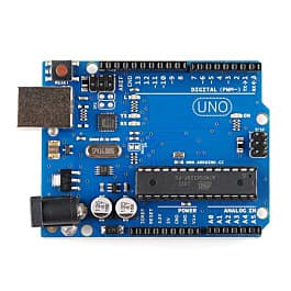
Microcontrollers like an Arduino UNOR3 or ESP32 can only supply a small amount of current (typically under 200 mA total from their 5V/3.3V power rails). A small SG90 micro servo can draw 100 mA to 250 mA under light movement, but under load or stall conditions, it can spike above 600 mA. Larger metal-gear servos like the MG996R can easily draw 1.5 Amps to 2.5 Amps under load.
If you connect a servo directly to your microcontroller's 5V pin, the current draw will cause the microcontroller's voltage regulator to drop. This leads to brownouts (unintended micro-controller resets), erratic servo behavior, or permanent board damage.
Always power your servo motors using an external power supply, such as a 5V/6V battery pack or a dedicated DC power adapter rated for sufficient amperage.
2. Always Connect Grounds Together (Common Ground)
When using an external power source for your servos while using a microcontroller for control signals, you must connect the Ground (GND) of the external power supply directly to the Ground (GND) pin of the microcontroller.
Without a common ground reference, the microcontroller's signal pin cannot establish a clean voltage benchmark, causing the servo to jitter uncontrollably or fail to respond.
Controlling a Servo Motor with Arduino
Below is a practical setup and code example showing how to control a positional servo motor using an Arduino UNO board.
Wiring Diagram Setup
- Connect the Red wire (+5V/6V) of the servo to the positive terminal of your external battery supply.
- Connect the Black/Brown wire (GND) of the servo to the negative terminal of your external battery supply.
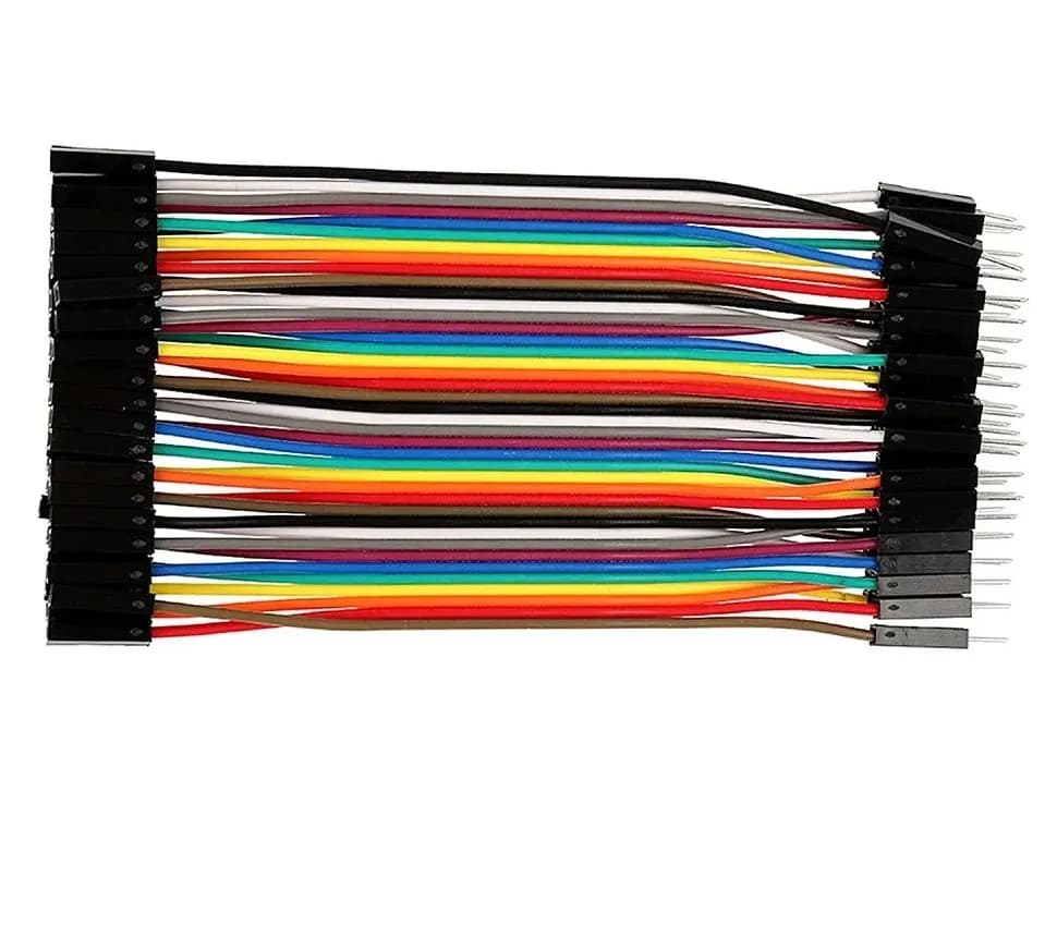
- Connect a jumper wire from the negative terminal of your external battery supply to an Arduino GND pin.
- Connect the Yellow/Orange/White wire (Signal) of the servo to Digital Pin 9 on the Arduino.
+------------------+         +-------------------+
|  External Power  |         |   Arduino Board   |
|   Supply (5V)    |         |                   |
|                  |         |                   |
|   (+)        (-) |         | Pin 9       GND   |
+----+----------+--+         +---+----------+----+
     |          |                |          |
     |          +----------------+----------+
     |          |                           |
     |          v                           |
+----+----------+---------------------------+----+
|   Red       Black/Brown               Yellow   |
|  (Power)      (Ground)               (Signal)  |
|                                                |
|                   Servo Motor                  |
+------------------------------------------------+
Example Code: Sweeping a Servo Motor
The following C++ program uses the built-in Arduino Servo.h library to smoothly sweep the motor shaft back and forth from 0° to 180°.
#include <Servo.h>

// Create a servo object to control a servo motor
Servo myServo;

// Store the motor position in degrees
int currentAngle = 0;

void setup() {
  // Attach the servo object to digital pin 9
  myServo.attach(9);
}

void loop() {
  // Sweep from 0 degrees to 180 degrees
  for (currentAngle = 0; currentAngle <= 180; currentAngle += 1) {
    myServo.write(currentAngle); // Tell servo to go to position in variable 'currentAngle'
    delay(15);                   // Wait 15 ms for the servo to reach the position
  }

  // Sweep back from 180 degrees to 0 degrees
  for (currentAngle = 180; currentAngle >= 0; currentAngle -= 1) {
    myServo.write(currentAngle); // Tell servo to go to position in variable 'currentAngle'
    delay(15);                   // Wait 15 ms for the servo to reach the position
  }
}
Code Explanation
#include <Servo.h>imports the built-in library, handling the background PWM signal timing.myServo.attach(9)sets Pin 9 as the PWM control line.myServo.write(angle)sends the signal translating to the desired angle (from 0 to 180).delay(15)allows time for the physical mechanism to move to the targeted angle before receiving the next increment command.
Servo Motors vs. Stepper Motors vs. DC Motors
Choosing the right motor depends on your robot's mechanical requirements. Here is a comparison to help you decide when to use a servo motor versus other motor types:
| Feature | Servo Motor | Standard DC Motor | Stepper Motor |
|---|---|---|---|
| Rotation Range | Typically 0° to 180° (or continuous) | Continuous 360° | Continuous 360° |
| Positioning Accuracy | High (Closed-Loop) | Low (Needs external encoders) | High (Open-Loop step counting) |
| Torque at Rest | Maintains high holding torque | Zero holding torque | High holding torque |
| Complexity | Simple control (3 wires, simple PWM) | Needs H-Bridge driver board | Needs dedicated Stepper Driver board |
| Best Robotics Use | Robot arms, steering, pan-tilt heads | Drive wheels, fans, propellers | 3D printers, CNC tools, precise linear slides |
Common Beginner Mistakes and Troubleshooting
If your servo motor is not responding correctly, check these common points:
1. Motor Jittering or Buzzing
- Cause A: Unstable power supply. If your battery level drops, the servo circuit struggles to hold position.
- Cause B: Mechanical binding. If the robot arm hits a physical obstruction, the servo continuously fights to reach its target position, drawing high current and buzzing.
- Cause C: Signal noise. Long signal wires without a clean common ground can cause erratic positioning signals.
2. Arduino Resets Whenever the Servo Moves
- Cause: The servo is wired directly into the Arduino's 5V pin. The high current draw drops the supply voltage, forcing the microcontroller board to reboot. Use a dedicated external power supply for the motor.
3. Servo Moves to One Extremity and Stalls
- Cause: Sending pulse signals outside the physical limits of the servo. While 1000 µs to 2000 µs pulse widths are standard, some cheap hobby servos mechanical limits lie between 1050 µs and 1950 µs. Driving a servo past its internal mechanical stop will stall the motor and damage the gears.
Frequently Asked Questions (FAQ)
Can I convert a 180-degree positional servo into a continuous rotation servo?
Yes, but it requires mechanical modifications. You must open the servo case, remove the physical plastic stop on the main output gear, and modify or replace the internal potentiometer with fixed-value resistors to create a permanent center reference. However, purchasing pre-configured 360-degree continuous rotation servos is usually safer and more reliable.
How much torque do I need for my robot's joint?
Torque is measured in kilogram-centimeters (kg·cm) or Newton-meters (N·m). A rating of $5\text{ kg}\cdot\text{cm}$ means the servo shaft can hold a 5 kg mass attached to a lever arm 1 cm long (or 1 kg mass at 5 cm distance). Calculate the maximum distance of your robot arm and multiply it by the weight it must lift, then select a servo with at least double that calculated torque to ensure reliable performance.
Do I need a servo driver shield to control multiple servos?
If your project uses 1 or 2 servos, your microcontroller pins can handle them directly. However, if you are building a hexapod walker or an multi-axis robotic arm with 6 to 16 servos, use a dedicated servo driver module (like an PCA9685 I2C driver board). This reduces pin usage on your microcontroller to just two communication lines while offloading signal generation to an onboard chip.
Summary and Next Steps
Servo motors provide precise angular control, holding torque, and built-in position feedback, making them indispensable components in robotics. By pairing them with proper external power sources and control libraries, you can build reliable, smooth, and robust robotic systems.
To start building with servo motors:
- Wire up a micro servo (like an SG90) with an external power pack and an Arduino.
- Experiment with controlling the motor using simple sweep scripts.
- Add an analog input device, such as a potentiometer or joystick, to dynamically control the servo angle in real time.