What is SPI and I2C Protocols
Beginner-friendly guide to ESP32, its features, setup, and first IoT projects.

Welcome to the fascinating world where electronic components communicate with each other! Just like people use languages and rules to talk, microcontrollers, sensors, and displays use specific "protocols" to exchange information. Without these established rules, it would be a chaotic mess of electrical signals, and nothing would work.
Among the many communication protocols out, two stand out for their widespread use in embedded systems, DIY electronics, and robotics: SPI (Serial Peripheral Interface) and I2C (Inter-Integrated Circuit). Understanding these protocols is a fundamental step for anyone diving into electronics.
The Language of Electronics: Communication Protocols
At its core, a communication protocol is a set of rules and guidelines that allow two or more electronic devices to exchange data. These rules define how data is formatted, how it's sent, how it's received, and how errors are handled. Think of it like a traffic law for data — it ensures that information travels smoothly and reliably from one point to another.
In the world of microcontrollers, we often encounter the terms "master" and "slave" when discussing communication.
- Master Device: This device initiates the communication, controls the clock signal, and typically sends commands or requests data. It's like the conductor of an orchestra.
- Slave Device: This device responds to the master's requests, performs actions, or sends data when asked. It's like the musicians playing their instruments according to the conductor's lead.
Now, let's dive into the specifics of SPI and I2C.
What is SPI (Serial Peripheral Interface)?
Imagine you're trying to communicate with a friend using walkie-talkies. You have one channel to speak and another to listen, allowing both of you to talk and listen simultaneously. SPI works similarly, offering a fast, full-duplex communication method for devices to exchange data.
SPI is a synchronous serial communication protocol. "Synchronous" means that a shared clock signal (SCLK) synchronizes the data transfer between devices. "Serial" means that data is sent one bit at a time over a single data line, rather than multiple bits in parallel.
Image: Diagram showing an SPI Master connected to two SPI Slaves, illustrating SCLK, MOSI, MISO, and individual CS lines. URL: `https://i.imgur.com/SPI_Master_Slave_Diagram.png`
How SPI Works
SPI typically involves one master device and one or more slave devices. The communication happens over four dedicated wires:
- SCLK (Serial Clock): This line carries the clock signal generated by the master device. Both master and slave use this clock to synchronize data transfer. Each clock pulse causes a single bit of data to be transmitted.
- MOSI (Master Out, Slave In): This is the data line where the master sends data to the slave. Data flows from the master to the slave.
- MISO (Master In, Slave Out): This is the data line where the slave sends data back to the master. Data flows from the slave to the master.
- SS/CS (Slave Select / Chip Select): This line is used by the master to select which slave device it wants to communicate with. When the SS line for a particular slave is pulled low (active-low), that slave is enabled and ready to communicate. Each slave device needs its own separate SS line.
Practical Example: Communicating with an SD Card Module
Let's say you want your microcontroller (the master) to save sensor data to an SD card (a slave device).
- The microcontroller pulls the SD card's CS line low to select it.
- It then generates a clock signal on the SCLK line.
- To write data, the microcontroller sends bits one by one over the MOSI line, synchronized with the SCLK.
- To read data (e.g., file contents), the SD card sends bits one by one over the MISO line, also synchronized with the SCLK.
- Once the communication is complete, the microcontroller pulls the CS line high to deselect the SD card.
This dedicated setup for sending (MOSI) and receiving (MISO) allows SPI to achieve full-duplex communication, meaning data can be sent and received simultaneously. This makes it very efficient for high-speed data transfers.
Advantages of SPI
- High Speed: Because it uses separate lines for sending and receiving data (MOSI and MISO), and often has faster clock speeds, SPI is generally much faster than I2C.
- Full-Duplex Communication: Data can be sent and received at the same time.
- Simplicity: The hardware implementation is relatively simple, as it doesn't require complex addressing schemes or "acknowledge" bits like I2C.
- No Start/Stop Bits: Data frames are simpler, reducing overhead.
Disadvantages of SPI
- More Wires: Each slave device requires its own dedicated SS/CS line, meaning as you add more slave devices, the number of wires (and microcontroller pins) increases.
- No Acknowledgment: The master doesn't inherently know if a slave device actually received the data unless the slave is programmed to send a specific response.
- Short Distances: Best suited for communication over short distances within a circuit board.
Common SPI Devices
You'll often find SPI used with:
- SD Card Modules: For storing and retrieving data.
- Flash Memory: For non-volatile storage.
- LCD and OLED Displays: For high-speed screen updates.
- Certain Sensors: Like accelerometers or gyroscopes that require fast data rates.
- Analog-to-Digital Converters (ADCs) and Digital-to-Analog Converters (DACs).
What is I2C (Inter-Integrated Circuit)?
Now, let's shift our analogy. Imagine a library where there's one librarian (the master) and many readers (the slaves) who all share the same two aisles to get books. When a reader wants a book, they first tell the librarian their unique ID number and what book they want. The librarian then brings it to them. Everyone uses the same aisles, but specific IDs ensure the right book goes to the right person.
I2C (pronounced "eye-squared-see") is another synchronous serial communication protocol, but it's designed for simplicity and reducing the number of wires required. It's often referred to as a "two-wire interface" because it primarily uses just two wires for communication, regardless of how many devices are connected.
Image: Diagram showing an I2C Master connected to multiple I2C Slaves, illustrating shared SDA and SCL lines with pull-up resistors. URL: `https://i.imgur.com/I2C_Master_Slave_Diagram.png`
How I2C Works
I2C also operates with master and slave devices, but it's unique in that it supports multi-master communication, meaning multiple masters can share the bus, though only one can actively communicate at a time. The communication lines are:
- SCL (Serial Clock): Similar to SPI, this line carries the clock signal generated by the master to synchronize data transfer.
- SDA (Serial Data): This is a single data line used for both sending and receiving data. Data flows bidirectionally over this line.
Unlike SPI, I2C devices typically require pull-up resistors connected to both the SCL and SDA lines. These resistors ensure the lines are held "high" (at a positive voltage) when no device is actively pulling them "low." This is essential for the open-drain design of I2C.
Addressing Slaves
Since all slaves share the same data lines, how does the master know which slave to talk to? This is where device addresses come in. Each I2C slave device has a unique 7-bit (sometimes 10-bit) address.
When the master wants to communicate with a specific slave:
- The master sends a "START" condition (a specific signal on SDA while SCL is high).
- It then broadcasts the 7-bit address of the slave it wants to talk to, followed by a single bit indicating whether it wants to read from or write to the slave.
- All slave devices on the bus "listen" to this address. Only the slave with the matching address responds by sending an ACK (Acknowledge) bit back to the master. This ACK bit confirms that the slave is present and ready to communicate.
- Once the connection is established and acknowledged, the master and the selected slave exchange data over the SDA line, synchronized by the SCL line.
- After the data transfer, the master sends a "STOP" condition (another specific signal) to release the bus.
Practical Example: Reading Temperature from a Sensor
Let's say you have a temperature sensor (a slave) connected to your microcontroller (the master) via I2C.
- The microcontroller sends a START condition.
- It then sends the temperature sensor's unique I2C address, followed by a "write" bit, over the SDA line.
- The temperature sensor, recognizing its address, sends an ACK bit back.
- The microcontroller then sends a command (e.g., "read temperature register") to the sensor over SDA.
- The sensor sends another ACK.
- To read the actual temperature data, the microcontroller sends another START condition and the sensor's address again, but this time with a "read" bit.
- The sensor acknowledges, and then starts sending the temperature data bits over the SDA line, one by one, synchronized by the SCL.
- The microcontroller receives the data and sends an ACK for each byte received (except the last one, for which it typically sends a NACK (Not Acknowledge) to signal the end of its read request).
- Finally, the microcontroller sends a STOP condition to end the communication.
Because SDA is used for both sending and receiving, I2C is typically a half-duplex protocol; devices cannot send and receive data simultaneously.
Advantages of I2C
- Fewer Wires: Only two wires (SDA and SCL) are needed for communication, regardless of the number of slave devices (up to 128 devices with 7-bit addressing). This saves valuable microcontroller pins.
- Device Addressing: Each slave has a unique address, allowing the master to selectively communicate with any device on the bus.
- Built-in Acknowledgment: The ACK/NACK system provides reliable communication by confirming that data bytes have been received.
- Multi-Master Capability: Multiple masters can share the same bus (with arbitration to prevent conflicts).
Disadvantages of I2C
- Slower Speed: Generally slower than SPI due to the addressing overhead, start/stop conditions, and half-duplex nature.
- More Complex Software: The software implementation is more complex due to the addressing scheme and ACK/NACK handling.
- Pull-up Resistors Required: Requires external pull-up resistors, which adds a tiny bit of component count and board space (though many modules integrate them).
- Capacitance Limitations: The total capacitance of the bus limits the maximum speed and number of devices.
Common I2C Devices
I2C is incredibly popular for connecting:
- RTC (Real-Time Clock) Modules: For keeping track of time.
- EEPROMs: For small amounts of non-volatile storage.
- Temperature, Humidity, Pressure Sensors: Such as BMP180, BME280, DHT12.
- Accelerometers and Gyroscopes: Like MPU6050.
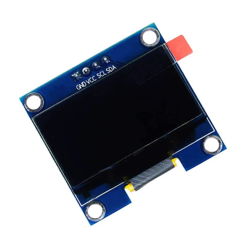
- Small OLED Displays: For displaying information.
- Port Expanders: To add more GPIO pins to your microcontroller.
SPI vs. I2C: Choosing the Right Protocol
When should you use SPI, and when is I2C a better choice? The decision often comes down to balancing speed, the number of wires, and system complexity. Here's a comparison to help you decide:
| Feature | SPI (Serial Peripheral Interface) | I2C (Inter-Integrated Circuit) |
|---|---|---|
| Number of Wires | 4 (SCLK, MOSI, MISO, CS/SS per slave) | 2 (SCL, SDA) |
| Master(s) | Single Master | Single or Multi-Master (with arbitration) |
| Slave(s) | Multiple slaves, each with its own CS/SS line | Multiple slaves, each with a unique 7/10-bit address |
| Communication Type | Full-Duplex (simultaneous send/receive) | Half-Duplex (send OR receive at one time) |
| Speed | Generally faster (up to tens of MHz) | Generally slower (typically up to 400 kHz, 1 MHz) |
| Addressing | No explicit slave addressing; uses CS/SS lines | Slaves are addressed by unique 7-bit or 10-bit ID |
| Acknowledgment | No built-in ACK from slave | Built-in ACK/NACK mechanism |
| Complexity (Hardware) | More pins required on master for multiple slaves | Fewer pins required on master |
| Complexity (Software) | Simpler (no addressing, less overhead per byte) | More complex (start/stop conditions, addressing, ACK) |
| Distance | Best for short distances on a PCB | Best for short distances on a PCB |
| Pull-up Resistors | Not typically required | Required on SCL and SDA lines |
| Typical Use Cases | High-speed data transfer: SD cards, displays, flash memory, ADCs/DACs | Connecting multiple low-speed sensors, RTCs, EEPROMs, port expanders, small displays |
Conclusion
SPI and I2C are powerful and widely used serial communication protocols that enable a vast array of electronic devices to interact seamlessly. SPI offers blazing fast, full-duplex communication with dedicated lines for each function, making it ideal for applications requiring high data rates, like driving displays or reading/writing to memory. I2C, on the other hand, excels in simplicity and wire efficiency, allowing many devices to share just two wires, perfect for connecting multiple sensors or low-speed peripherals that don't need constant, high-volume data exchange.
Understanding these protocols is a cornerstone for anyone venturing into embedded systems development. By knowing their strengths and weaknesses, you can confidently choose the right communication method for your next electronics project.
Next Steps
Now that you have a foundational understanding of SPI and I2C, the best way to solidify your knowledge is to get hands-on!
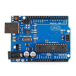
- Get a Microcontroller: An Arduino or ESP32 board is an excellent starting point.
- Acquire a Sensor/Module: Pick up a simple I2C sensor (like a BME280 temperature/humidity sensor) or an SPI device (like an SD card module).
- Find Example Code: Most development boards have extensive libraries and examples for both SPI and I2C. Try connecting your sensor and writing a small program to read data from it.
- Experiment: See how many I2C devices you can connect to a single bus, or how an SPI display updates quickly.