How to use the RC filter calculator
- Choose Low-pass (passes slow signals, blocks fast ones) or High-pass (blocks DC and slow signals, passes fast ones).
- Choose what to calculate: Find fc from R and C, or Find R / Find C for a cutoff frequency you want. When solving for a part, you also get the nearest standard value (E24 resistors, E12 capacitors) and the real cutoff it gives.
- Enter a signal frequency to check to see the gain in dB, the output-to-input ratio, the phase shift and — if you enter an input amplitude — the output voltage.
The Bode plot uses a logarithmic frequency axis. The black dot marks the −3 dB cutoff point, the grey dashed lines are the straight-line approximation, and the blue dot is your test frequency.
Formula
fc = 1 ÷ (2π × R × C) τ = R × C, fc = 1 ÷ (2πτ)
Low-pass: |H| = 1 ÷ √(1 + (f/fc)²) phase = −arctan(f/fc)
High-pass: |H| = (f/fc) ÷ √(1 + (f/fc)²) phase = 90° − arctan(f/fc)
Gain in dB = 20 × log₁₀ |H|
At f = fc both filters give |H| = 1/√2 = 0.707, which is −3 dB. Far past the cutoff, a single RC stage changes by 20 dB per decade (a factor of 10 in voltage for every 10× in frequency).
| f compared with fc | Low-pass gain | High-pass gain |
|---|---|---|
| fc ÷ 10 | −0.04 dB (99.5%) | −20.0 dB (9.95%) |
| fc ÷ 2 | −0.97 dB (89.4%) | −6.99 dB (44.7%) |
| fc | −3.01 dB (70.7%) | −3.01 dB (70.7%) |
| 2 × fc | −6.99 dB (44.7%) | −0.97 dB (89.4%) |
| 10 × fc | −20.0 dB (9.95%) | −0.04 dB (99.5%) |
| 100 × fc | −40.0 dB (1.0%) | ≈ 0 dB (100%) |
Where RC filters are used
- PWM to analog — turning an Arduino or ESP32 PWM output into a voltage. Work out the duty cycle with the PWM duty cycle calculator.
- Sensor smoothing — a low-pass in front of an ADC input removes noise. Check the reading with the ADC voltage calculator.
- Audio coupling — a high-pass (series capacitor) blocks DC between amplifier stages while passing sound.
Common mistakes
- Forgetting the 2π. τ = RC is not the same as 1/fc. 10 kΩ and 100 nF give τ = 1 ms but fc = 159 Hz, not 1 kHz.
- Loading the filter. The formula assumes the next stage draws almost no current. Keep its input resistance at least 10× R, or add an op-amp buffer.
- Ignoring the source resistance. Whatever drives the filter adds its own resistance to R and lowers fc.
- Expecting a brick wall. One RC stage rolls off gently. Signals just above fc still get through at reduced size.
Learn more
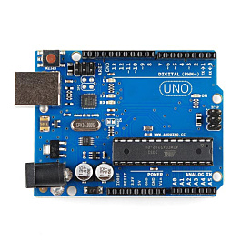
See how fast the same R and C charge with the RC time constant calculator, and read PWM explained: LED dimming and motor speed and capacitors explained for beginners. Want to try it on a real board? Our Arduino kits include the resistors and capacitors you need.